Menu
Traditionally, generating low-level electric fields in the 18 – 40 GHz frequency band has been performed using traveling wave tube amplifiers (TWTA’s). These TWTAs often produce much more power than is actually required to generate the required field strengths while also being an extremely costly solution. Why pay for unnecessary power? AR rf/microwave Instrumentation has the answer by introducing its AA-Series field generating systems. These systems can produce field strengths of up to 50 V/m in the 18 – 26.5 GHz and 26.5 – 40 GHz bands. An AA system is composed of a solid-state amplifier and antenna combined in a single housing, which can then be paired with a rack-mountable power and RF routing unit.
The AA-Series products are designed to be a low-cost and highly reliable solution to a decades-old problem of using costly, unreliable TWTAs to generate low-level, high-frequency electric fields. Typically, in the 18 – 26.5 GHz (K-Band) and 26.5 – 40 GHz (Ka-Band), the smallest-size TWTA available in terms of RF power is about 40 W, which provides a solution for field strengths up to 200 V/m. Until recently, this has been the only solution for generating any electric fields in these frequency bands. Up to this time, solid-state RF amplifiers at these frequencies and power levels were not available. However, this has changed with AR maximizing the potential of the latest technological advances. The AA-Series can produce field strengths of up to 50 V/m at 1 meter from 18 – 26.5 GHz and 26.5 – 40 GHz at almost a third of the price as ‘low-power’ TWTAs. Remember, too, that TWTA failures can result in months of downtime while they are repaired. This solid-state solution offers a significantly higher mean time between failure (MTBF) and much shorter repair times.
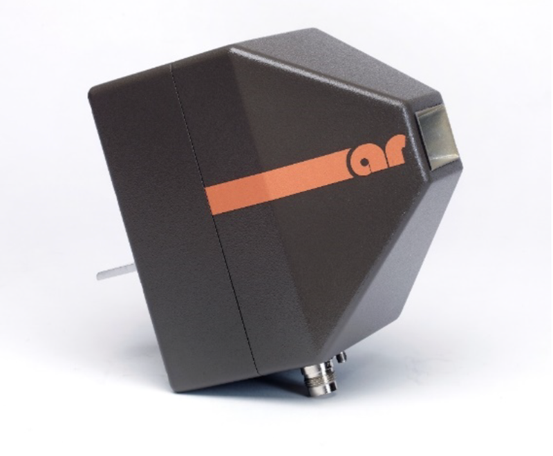
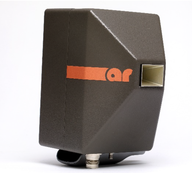
The AA18G26 and AA26G40 each consist of an antenna directly mounted to a solid-state amplifier, along with sufficient heat sink and overtemperature fault detection. By connecting the antenna directly to the amplifier, we have eliminated cable losses and can deliver maximum amplifier power to the antenna. Within each frequency band, there are two available options. The -20 and -50 options indicate the guaranteed minimum field strength (20 V/m or 50 V/m) that each unit delivers. The AA-Series uses antenna gain to minimize cost rather than amplifier gain to achieve higher field strengths. Table 1 lists all the available AA field generating units with their associated frequency ranges, field strengths, and antenna spot sizes.
| Model Number | Frequency Range (GHz) | Guaranteed Field Strength (V/m) | Spot Size (m) |
|---|---|---|---|
| AA18G26-20 | 18 - 26 | 20 | 0.31 x 0.31 |
| AA18G26-50 | 18 - 26 | 50 | 0.14 x 0.17 |
| AA26G40-20 | 26 - 40 | 20 | 0.29 x 0.32 |
| AA26G40-50 | 26 - 40 | 50 | 0.15 x 0.17 |


To interface with the AA18G26 and AA26G40 models, AR has designed the AA1000 (Figure 3). This unit is designed for routing RF and providing DC power to the amplifier and internal cooling fans to all AA-series models. For RF, the AA1000 receives RF from an external signal source and distributes the signal through a switch before leaving the unit and traveling to an AA18G26 or AA26G40 via provided low-loss coaxial cables. This switch acts as an automatic shut-off when faults are detected. Faults are determined by monitoring the DC power delivered to the amplifier and cooling fans. The DC power is generated by internal power supplies and delivered to the unit via provided twinax cables. It is controlled either by the front panel or remote control through GPIB, RS-232, Fiber Optic, USB, and Ethernet. A System Interlock is also provided. Using AR’s EMC software suite, emcware, an AA system communicates in the same manner as an AR amp, thus further ensuring the ease of incorporation into a laboratory’s test setup.

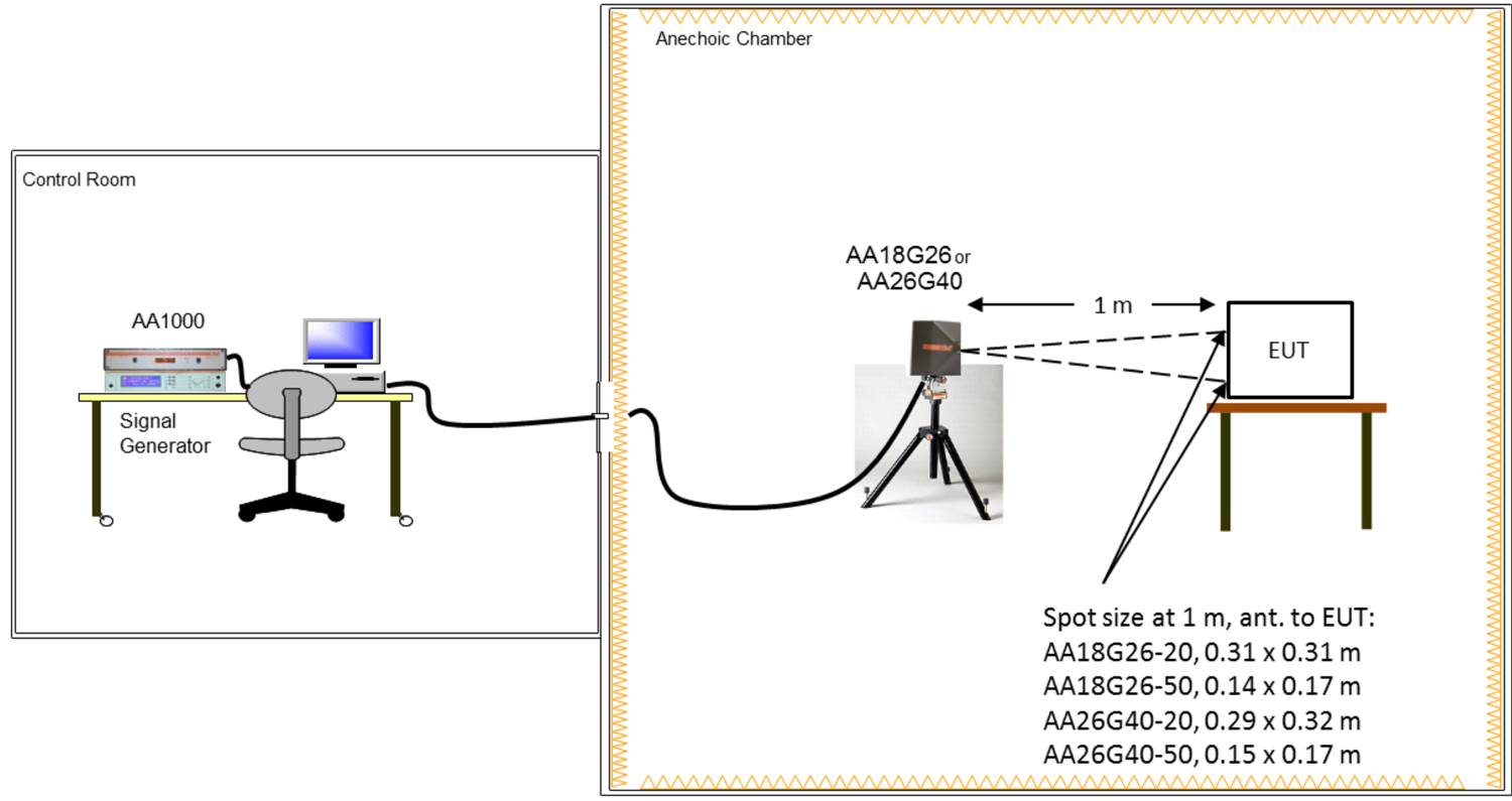
For all of the capabilities described above, the implementation of AA-series equipment is quite simple. Figure 4 provides a basic block diagram of the setup. All of the equipment highlighted in orange is provided by AR.

As was already stated, the AA-series was developed as a reliable, low-cost solution for testing low field strengths in the 18 – 26.5 GHz and 26.5 – 40 GHz frequency range. This includes a large variety of applications. First and foremost, the AA-series satisfies several requirements of RS103 of MIL-STD-461. Specifically, the following Platform test levels can be met:
These requirements are all met with minimal change to the typical test setup for RS103. It should be noted that these changes resulting from using AA-series equipment are acceptable per MIL-STD-461. Figure 5 shows a typical RS103 test setup utilizing AA-series equipment.

Please be aware that RS103 is not the only application for the AA-series. With today’s evolving marketplace, technology is continuing to see contributing threats at higher operating frequencies. One such example is 5G. It’s well known that 5G is on its way, and it will be utilizing bandwidth in the Ka-band. Other communication types, such as satellite communications, are already moving into the K and Ka-bands to utilize speed and wider bandwidths. Many current and future radar applications exist in the K and Ka bands as well. Many EMC standards are also beginning to move higher in frequency to accommodate these changes in operational frequencies.
To rectify a decades-old problem of expensive and unreliable TWTAs, AR has developed a new solution for low-field strength radiated immunity testing from 18 – 40 GHz. The AA-series field generating systems can produce field strengths of up to 50 V/m in the 18 – 26.5 GHz and 26.5 – 40 GHz frequency bands. AA-series products utilize solid-state technology for a more reliable, low-cost option over traditional TWTA approaches. Furthermore, by using AR’s emcware, the system is controlled and monitored like any other ARI amplifier, making the overall operation easy for the test engineer. If you would like to learn more, feel free to contact one of our applications engineers at 800-933- 8181 or visit our website at www.arworld.us.
160 Schoolhouse Rd.
Souderton PA 18964-9990 USA
215.723.8181
[email protected]
[email protected]
Contact Us
For an applications engineer call:
800.933.8181
For Customer Service, call:
215.723.0275
For Faxing Orders:
866.859.0582 (Orders Only, Please)
Privacy Policy
Terms of Use
Copyright ©2023 AR Inc.