Menu
On September 2nd, 1837, Samuel Morse demonstrated a device for transmitting information by electromagnetic energy through conductive wires. 60 years later, Guglielmo Marconi founded the Wireless Telegraph & Signal Company, and since then, the world has never looked back. Progressive advancements have climbed the electromagnetic spectrum and pushed device technology to ever greater heights. This has been especially true since 1980 when cellular communications systems became commercially viable. This application note will explore some of the testing requirements for telecommunication devices and how to benefit from AR RF/Microwave Instrumentation’s products.
We will consider two broad categories of device testing: characterization and reliability. Characterization testing focuses on device performance as related to its operation in a defined and specified condition. Reliability testing aims to determine the life expectancy and limits of the device. This application note will focus on mid to high power systems (> 1W peak). Low power systems (<28dBm peak) such as Bluetooth, Zigbee, and LAN do not typically require test bench amplification.
Telecommunication system devices must be characterized over temperature, voltage, modulation, drive level, and frequency. Common test parameters are power saturation, isolation, and linearity. This generates a vast quantity of data, and thus a test system must be highly reliable and faithfully replicate the desired stimulus over the parametric range. AR amplifiers provide the widest frequency bandwidth (BW) in the industry and cover power levels from 1 W to well over 10 kW. Amplifiers Page
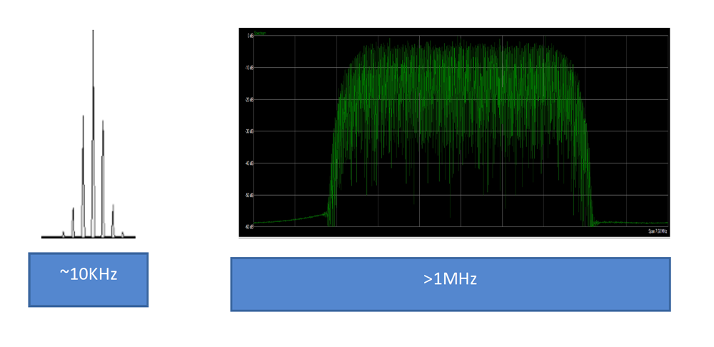
Common measurements are intermodulation or multi-tone (IM3/IP3/OP3), spectral emission mask (SEM), error vector magnitude (EVM), and adjacent channel leakage ratio (ACLR). For many decades, multi-tone, typically 2 tones, have been the principal metric in determining a device’s linearity. Early telecom methods did not contain much data, and analog modulation was enough. Modern digital modulation schemes continue to push data rates ever higher (see Figure 1), increasing the need for greater linearity over a large bandwidth and power range. AR amplifiers are predominantly Class A, providing the best possible linear amplification.

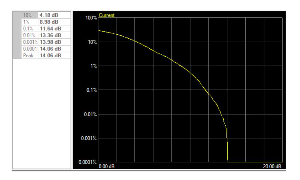
3rd Generation Partnership Project (3GPP) is the standards development body for mobile communications. Successive generations 3G, 4G to the current 5G chronicle this expansion of spectrum bandwidth. 3GPP defines the test models (TM) or modulation profiles for testing linear performance of user equipment (UE) and base station (BS), and by extension the devices used in those systems. 5G modulation schemes for both uplink and downlink range from channel width of 5 to 100MHz with peak to average ratios (PAR) up to 14dB. See Figure 2 below.

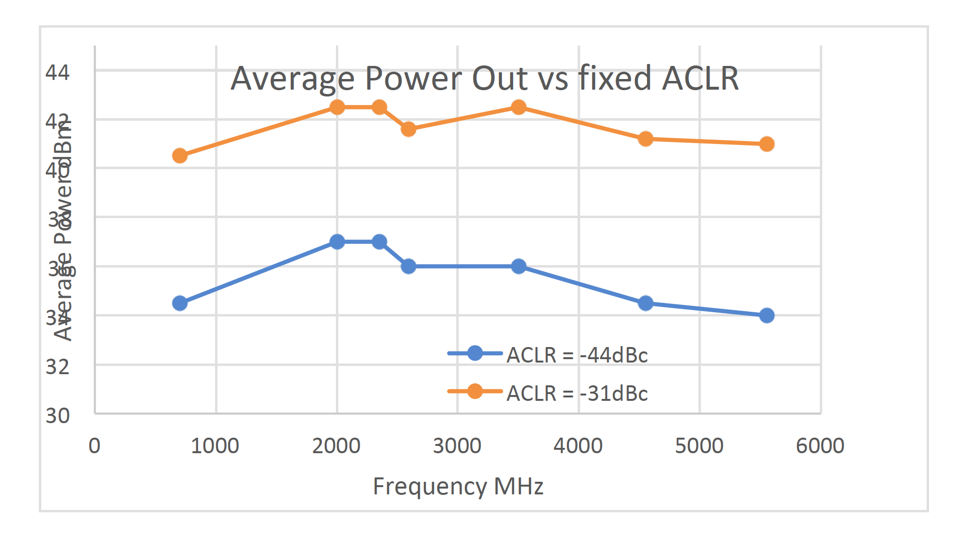
Channel power is specified by average power. High PAR therefore will require the lab amplifier to maintain good linearity to the peak value (avg power = 23dBm, PAR = 14dB, peak power = 37dBm). Figure 3 is a measurement of AR Model# 30S1G6 using TM 1.1. This plot shows the average power output for a given linear target. By comparison, Class AB power amplifiers are by nature less linear and are prone to gain expansion from small signal to max power. This adds to the distortion on high PAR modulations.

Multi-tone intermodulation measurements can benefit as well from a power amplifier. While this is a ‘small signal’ parameter, very high IP3 devices, such as a base station T/R switch, require a large dynamic range. For an input IP3 of 50 dBm and a total tone power of 0 dBm, IM products will be ~ -109dBm (dynamic range = 109dB). This can be difficult to measure accurately. By increasing RF drive while keeping level below saturation, IM products are exponentially increased and dynamic range reduced to a comfortable level (IIP3 = 50dBm, total tone power = 30dBm, IM product = -19dBm, dynamic range = 46dB). High power devices will also need drive amplification to measure deep saturation and isolation.
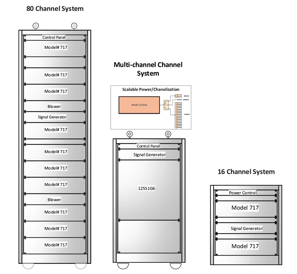
Long-term operating life, burn-in, and drive level failure are critical tests to determine a device’s reliability. High temperature operating life (HTOL) is the common method to determine the life cycle of a device. Burn-in is a method to weed out the weak product. Drive level failure determines a device’s susceptibility in its operational environment. Any of these tests require drive levels to meet or exceed the DUT maximum rating. Since device failure is an expected condition, the drive amplifier must withstand a possible short or open condition. AR amplifiers have long been known for their immunity to high VSWR. HTOL and burn-in tests are typically applied to many DUT’s at the same time. AR can offer RF distribution systems scalable from 8 to 80 channels. See Figure 4.

AR’s S-series line of amplifiers specifically targets existing cellular frequency bands (15 to 500 W). See Table 1 for a recommended model matrix matched to your testing requirement. We also have an extensive line to cover other frequencies as low as 10KHz and as high as 50 GHz. Please contact AR’s expert application team to ascertain the right model for your specific requirement.
| Model# | Linear Power (W) | Frequency Range (MHz) | Application | Testing Profiles |
|---|---|---|---|---|
| 15S1G6 | 15 | 600-6000 | User Equipment (UE) Mobile Handset | Pre-amp for Linearity Test IMD/ACLR/SEM/EVM |
| 30S1G6 | 30 | 600-6000 | Pre-amp for Linearity Test IMD/ACLR/SEM/EVM | Pre-amp for Linearity Test IMD/ACLR/SEM/EVM |
| 60S1G6 | 60 | 600-6000 | Macro-cell Base Station UE reliability | Pre-amp for Linearity Test IMD/ACLR/SEM/EVM UE HTOL/Burn-in |
| 125S1G6 | 125 | 600-6000 | UE and BS reliability | UE/BS HTOL/Burn-in |
| 250S1G6 | 250 | 600-6000 | UE and BS reliability | UE/BS HTOL/Burn-in |
| 500S1G6 | 500 | 600-6000 | UE and BS reliability | UE/BS HTOL/Burn-in |
Our products are the industry leader in warranty and reliability. Tolerance to RF loading to short or open condition is guaranteed under absolute maximum rating conditions. This is important in a test lab environment where the amplifier may be subject to high VSWR. Downtime is eliminated or reduced. Whatever your testing need, we have the solution either in our existing line or as a custom system solution. Contact AR application support anytime: [email protected].
160 Schoolhouse Rd.
Souderton PA 18964-9990 USA
215.723.8181
[email protected]
[email protected]
Contact Us
For an applications engineer call:
800.933.8181
For Customer Service, call:
215.723.0275
For Faxing Orders:
866.859.0582 (Orders Only, Please)
Privacy Policy
Terms of Use
Copyright ©2023 AR Inc.