Menu
Many hazardous electrical events in the environment can have adverse effects on a vehicle’s systems, causing potentially unsafe situations. These events can be generated by “off-vehicle” and “on-vehicle” sources and can either be natural or man-made. To protect against these events, automobile manufacturers have developed Electromagnetic Compatibility (EMC) standards to test electronic components and whole vehicles. Some known man-made events are the L-band & S-band Air Traffic Control Radar Pulses commonly used at or near airports. These high-intensity RF fields are directed up into the sky but sometimes can be detected on the surface where they could possibly affect automobile electronics.
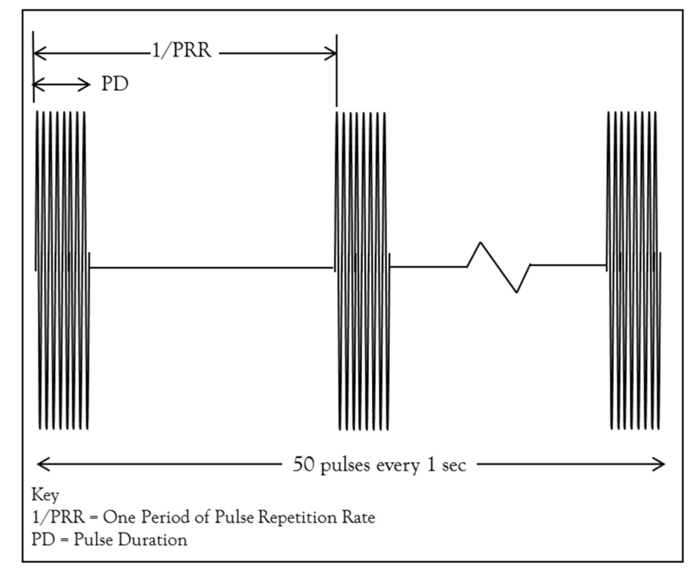
Both General Motors (GM) and Ford auto manufacturers have developed test specifications to test automobile components that may be exposed to an L-band or Sband radar pulse. These specifications are not identical, but they are very similar. See Table 1 and Figure 1 for details on these requirements.
| Manufacturer Spec | Frequency | Field Level | Antenna Distance | Pulse modulation | |
|---|---|---|---|---|---|
| GM GMW3097 | 1.2 - 1.4 GHz | N/A | 600V/m | 0.75 m | 300Hz Pulse Repetition Rate (PRR) 6ms Pulse Duration (PD) 50 pulses output every 1 sec |
| FORD EMC-CS-2009.1 | 1.2 - 1.4 GHz 2.7 - 3.1 GHz | 300V/m(1) | 600V/m(2) | 1 m | 300Hz PRR 3ms PD(3) 50 pulses output every 1 sec |
1 Level for most electronic equipment
2 Level for selected components associated with supplemental restraints including frontal crash
3 6µs Pulse duration used when testing in a Reverberation Chamber

AR RF/Microwave Instrumentation offers a wide range of EMC test products and accessories, covering DC to 60 GHz. Through knowledge gained over 40 years in the EMC industry, AR has developed products that work together most efficiently and produce the necessary field strengths to meet the respective standards and customer requirements. AR accomplishes this by participating in standards development activities, awareness of standards in various fields, knowledge of upcoming changes, and developing state of the art instrumentation products.
A testament to this expertise for developing the latest and specification specific products is the development of the 700S1G4 amplifier that operates from 0.7 GHz and provides over 700 W of Class A output power and the ATH800M5GA horn antenna. Combining these units allows accurate recreation of the L and S band pulsed radar threats defined by Ford and GM and presented in Table 1. Testing in this frequency range is usually required on a specific class of components whose lack of performance may directly impact personal safety. The device categories may vary among automotive manufacturers, but the examples discussed herein belong to Ford Motor Company and General Motors Company.
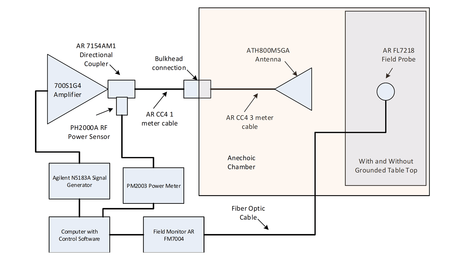
Rather than calculate the potential field strength for the ATH800M5GA and 700S1G4 combination, data was gathered with the antenna positioned inside an anechoic chamber and connected to the amplifier by 4 meters of AR CC4 coaxial cable. Various setup configurations were evaluated: vertical and horizontal antenna polarization, with and without grounded test benches, and with the antenna positioned 1 meter from the field probe. All of this testing was performed at an accredited testing laboratory. Figure 2 gives an illustration of the general setup of the tests.

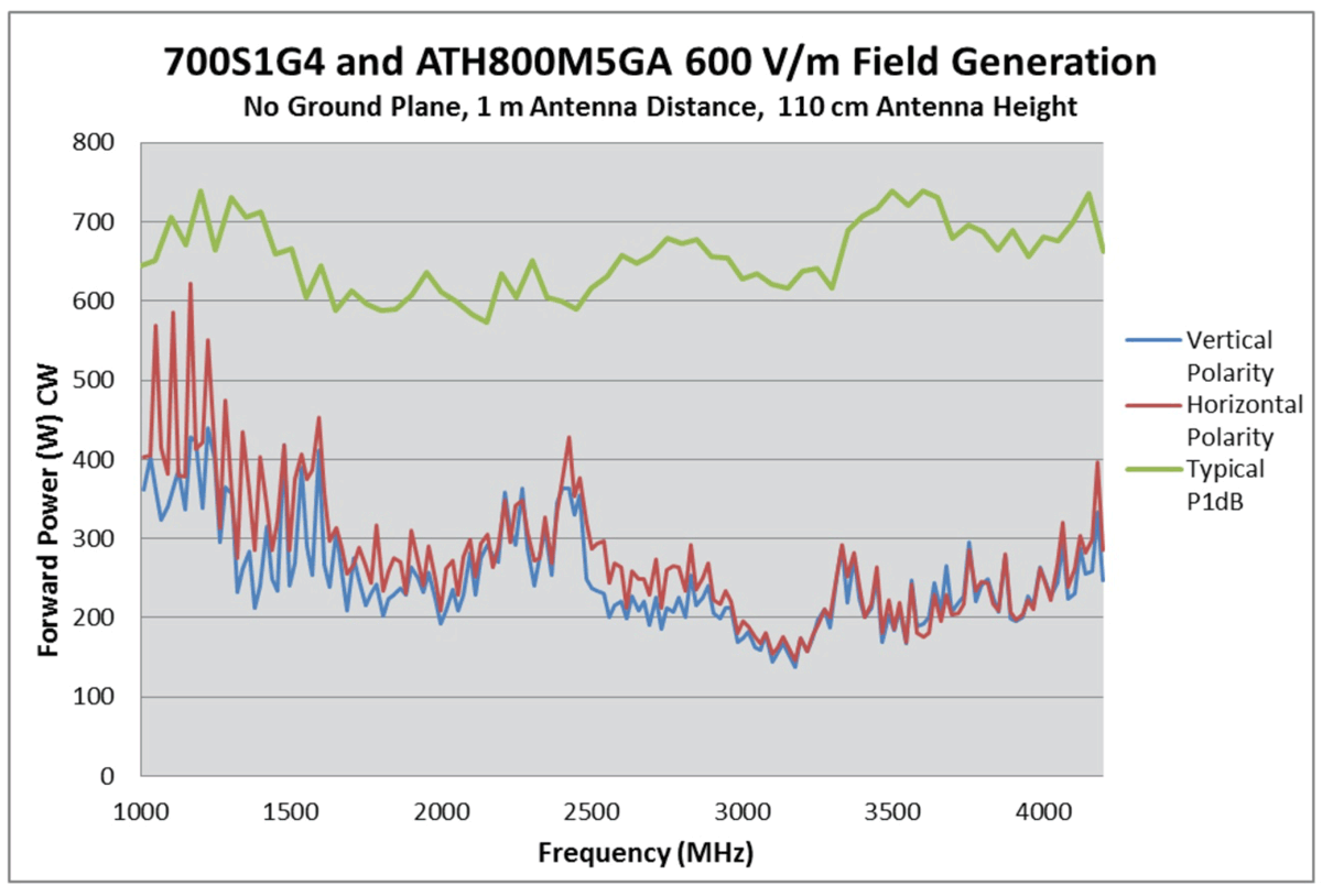
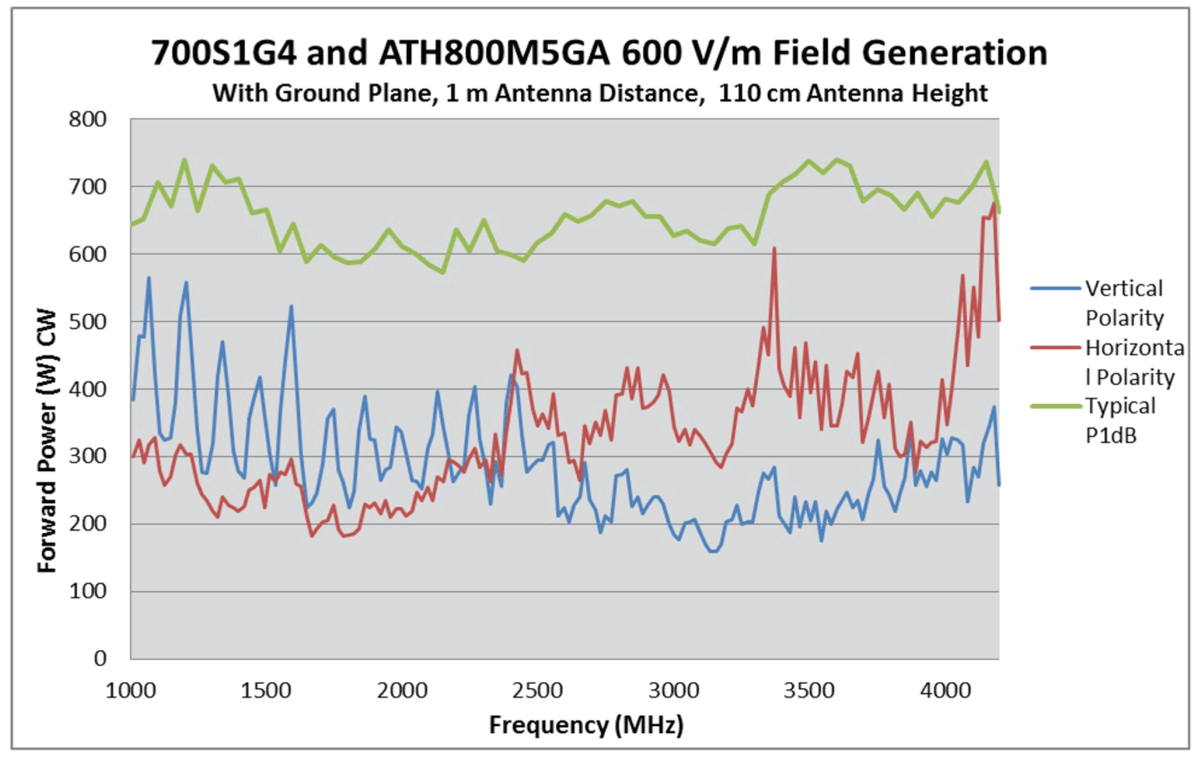
The results of this testing show that the combination of the 700S1G4 and ATH800M5GA easily meet the 600 V/m field strength requirement for pulsed L and S band radar testing. The data given in Figure 3 shows the forward power of the amp and antenna combination in the test setup configuration required for EMC-CS-2009.1 (i.e. no ground plane) while leveling on 600 V/m. Figure 4 also gives forward power while leveling on 600 V/m, but with a ground plane, thus satisfying the setup for GMW3097. For both test setups, the measured forward power data is compared against the amplifier’s typical P1dB to show that the amp is operating well within its linear region.


For performing L and S band pulsed radar testing at 600 V/m, AR RF/Microwave Instrumentation serves as a single-source for all of your test equipment needs. The 700S1G4 amplifier and the ATH800M5GA antenna have been proven to provide the necessary field levels under the required test configurations. AR can also provide the accessories necessary for completing the setup, such as directional couplers, cables and power meters.
160 Schoolhouse Rd.
Souderton PA 18964-9990 USA
215.723.8181
[email protected]
[email protected]
Contact Us
For an applications engineer call:
800.933.8181
For Customer Service, call:
215.723.0275
For Faxing Orders:
866.859.0582 (Orders Only, Please)
Privacy Policy
Terms of Use
Copyright ©2023 AR Inc.