Menu
Multi-tone testing has many benefits. While the multi-tone method was initially implemented to increase the speed of IEC 61000-4-3 radiated immunity testing, it has been found that this method also improves equipment efficiency, offers greater flexibility to truly test the equipment (EUT) under real-world threat conditions, and can be fully compliant to standards. Other benefits include more efficient use of finite financial and human resources and faster time-to-market for new and enhanced products.
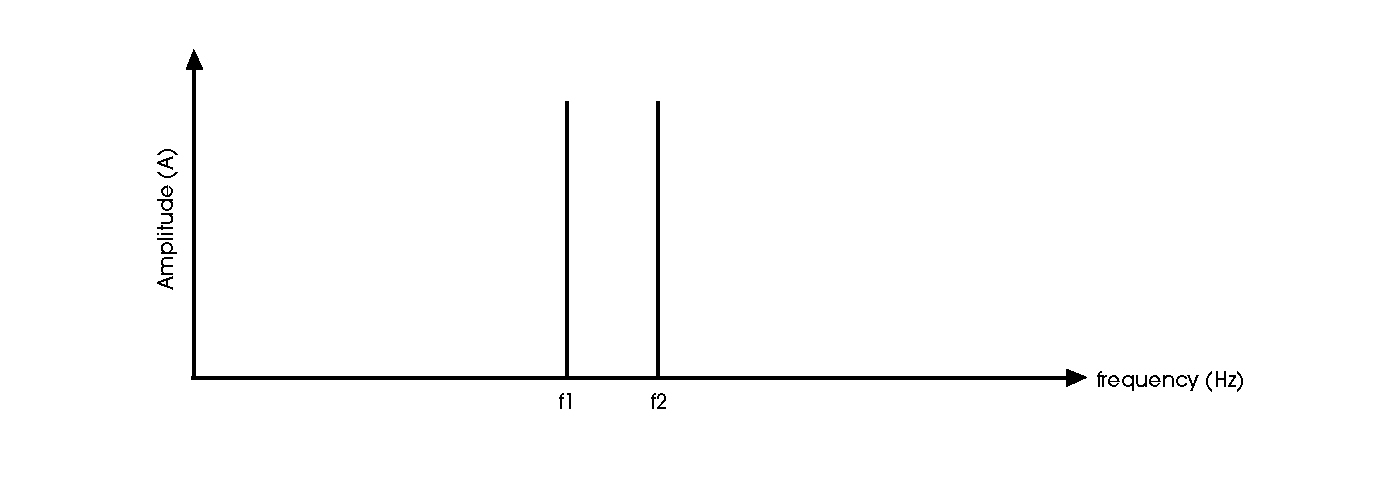
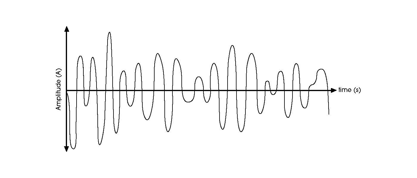
Multi-tone signals are multiple sine waves, or tones, each having a unique amplitude, phase, and frequency combined into one composite signal. Observations made in the frequency domain of a multi-tone signal will show each unique frequency, as depicted in Figure 1. Conversely, in the time domain, the multiple signals will appear as a composite signal in which each of the tones will add or cancel to make one signal seen in Figure 2.
Historically, amplifier selection for Electromagnetic Compatibility (EMC) testing was based mainly on tribal knowledge and information scattered across the EMC industry. However, proper EMC amplifier selection is an important step in achieving required RF levels. It should be noted that quality and support are of equal importance as features when selecting an amplifier. Down-time from equipment failures often means test lab’s throughput slows, thus impacting the lab’s profitability and customer schedules. Additional considerations are numerous. It is important to properly understand the following in order to make a proper decision:
Multi-tone testing is gaining popularity with test laboratories performing radiated immunity testing. Recently adopted by IEC 61000-4-3, multi-tone testing offers many benefits. By applying multiple signals at once, total time required to perform the test can be drastically reduced. Multi-tone testing may be used by test laboratories to improve efficiency of the equipment and human resources, or by manufacturers for performing pre-compliance testing at lightning speeds.
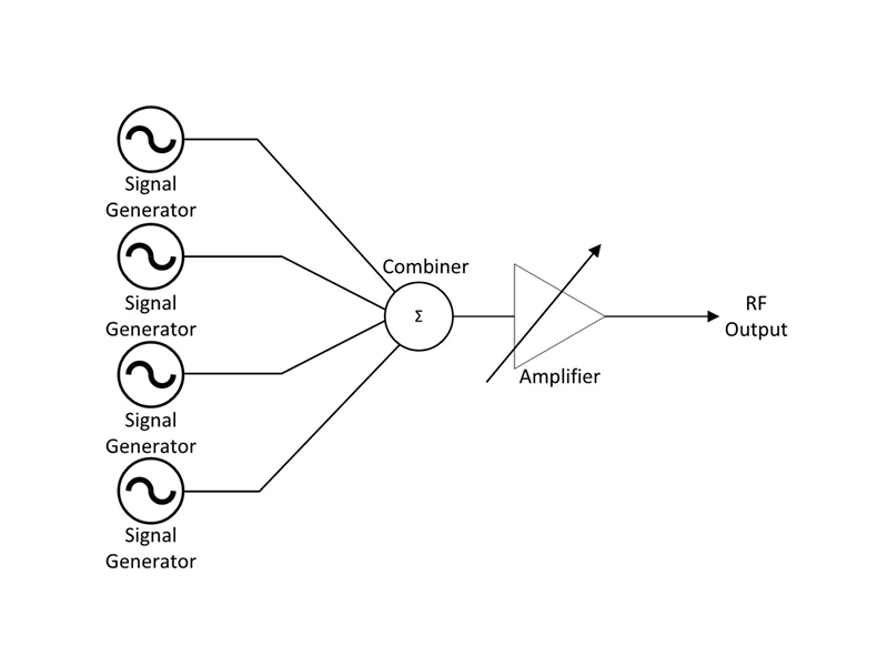
Using the traditional way to generate multiple signals, multiple independent CW generators are added together using a combiner. After the signals are combined, they are amplified and output as one signal, as shown in Figure 3. The multi-tone test system contains two or more signal generators that generate the signals. A large RF power amplifier is required, so the multi-tone signals are not distorted. In addition, either a vector signal analyzer or spectrum analyzer is needed to measure the power in the frequency domain because traditional power meters measure the broadband spectrum, including the harmonics and intermodulation products.
Many signal generators also offer various modulation types, including analog and composite (digital) modulation. Classic analog-modulation types include amplitude-modulation (AM), frequencymodulation (FM), phase-modulation (ΦM), and pulse-modulation signals. Modulation is important because it’s the information-carrying part of the signal.
The composite amplitude of multi-tone signal can be measured by the crest factor, which is defined as the ratio of the peak magnitude to the RMS value of the signals. Relative phases of each tone with respect to each other determine the multi-tone signal’s crest factor. A multi-tone signal with a large crest factor contains less energy than one with a smaller crest factor. Individual signal sine tones have lower signal-to-noise ratios with a higher crest factor. Proper selection of phase is critical to generate a useful multi-tone signal. The maximum number of tones needs to be considered to avoid amplitude clipping of the signal. You can use different combinations of phase relationship and amplitude to get a lower crest factor.
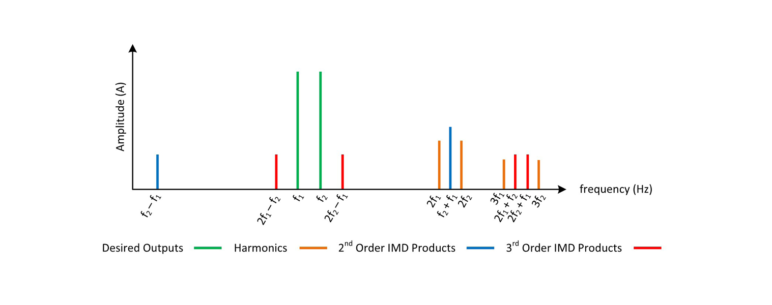
Intermodulation distortion (IMD) and harmonic distortion are types of nonlinear distortion. Intermodulation distortion results from unwanted intermodulation between multiple frequency tones that comprise a multi-tone signal. Harmonics are integer tones of the fundamental input signals generated when a signal passes through a nonlinear device.
Output signal tones of a device can be calculated from the input signal tone using a transfer function that provides a mathematical relationship between the output and input tones. Every transfer function can be described by a polynomial called the Taylor-series. Since the Taylorseries is infinite, the number of harmonics in the output, in theory, is infinite. Higher order harmonics amplitude decreases exponentially and thus can practically be ignored for multi-tone applications. When decreasing the input signal, the amplitude of the harmonic signal decreases exponentially by a factor of An.
Figure 4 shows what happens when two tones are input into a non-linear device. The intermodulation will form additional signals at multiples of the sum and difference of the original inputs. The mathematical equations of a two-tone intermodulation product follow.
Vo is the transfer function to determine the output signal based on the input signals
$V_0 = a_1v_i + a_2{v_i}^2 + a_3{v_i}^3 + …. a_n{v_i}^n$
The following equation is used to calculate two tone input.
The next equation is used to calculate the 2nd harmonic of two-tone input based on the addition theorem for the cosine function.
And the following equation is used to calculate the 3rd harmonic of two tone input.
Care must be taken to ensure that these unwanted signals do not significantly affect the quality of the immunity test. These intermodulation products can be minimized through the use of properly sized amplifiers.
The input power level of each tone of a multi-tone signal should be set by considering the number of tones and desired level of distortion that can be tolerated. The power required to generate multi-tone signals can be defined in both peak and average terms. The average power is defined as a sum of the power of each tone and distortion products. The peak power is the maximum instantaneous power of the combination of all the tones. Maximum peak power happens in the moment of time when all the voltage vectors from each of the tones are aligned. The power for average or peak is defined below. Note that this assumes that all the tones are equal in power.
$
P_{\text{MT_AVG}} \text{(Watts)} = P_{\text{ST_W}} * N
$
$
P_{\text{MT_AVG}} \text{(dBm)}=P_{\text{ST_dBm}} + 10 Log N
$
$
P_{\text{MT_PK}} \text{(Watts)} = P_{\text{ST_W}} * N^2
$
Where:
P MT_AVG = Average power of multi-tone signal
P MT_PK = Peak power of multi-tone signal
P ST_W = Power in Watts of single tone
P ST_dBm = Power in dBm of single tone
N = Number of tone signals
To reduce distortion, the peak power can be used to calculate the number of signals that any given amplifier can amplify. However, since the individual signals differ in frequency, their relative phase is constantly changing. The peak power level is only reached when all of the tone signal vectors are aligned; the more tones that are generated, the shorter the occurrence of the instantaneous peak power.
Intermodulation distortion occurs when the peak power can’t be reached. This distortion is minimized by only using amplifiers within their linear operating limits (P1dB). Ways to remedy this situation are to increase the size of the amplifier, reduce the power of the tones, or reduce the number of tones.
The linearity and harmonic checks of immunity standards can be used to determine the number of signals that a given amplifier can generate with acceptable distortion.
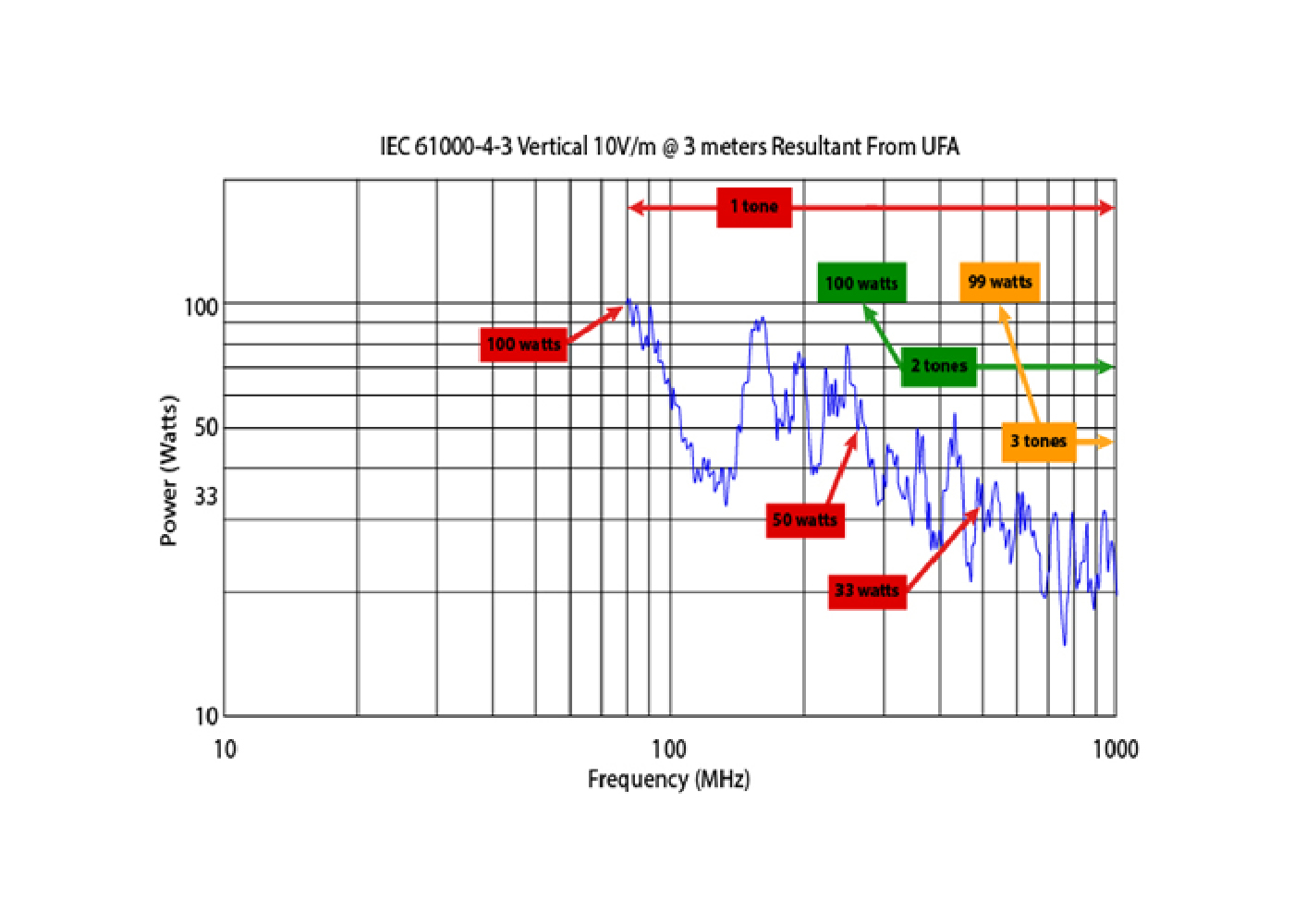
For immunity testing, the required power to generate a disturbance tone signal varies as a frequency function, as shown in Figure 5. Note that, due to antenna gain, the required power falls off rapidly with frequency. In this example, multi-tone testing can take advantage of the full power of the amplifier and reduce overall test time.
In the example shown in Figure 5, a 250 W amplifier provides a 2x speedup at the lower frequencies with a much greater reduction in test time at the higher frequencies. In many cases, test labs have the power to produce high RF fields but historically have not fully utilized that power because they are running single-tone tests, which require lower power levels. With multi-tone testing, test labs can make better use of their unused amplifier power while reducing test times. The justification for adding higher power amplifiers to the test lab has become a little easier because the high power amp will allow for testing at higher field levels and result in a reduction in test time and more efficient use of resources when utilizing multi-tone technology.
The concept of multi-tone testing is simple. Rather than generating a single frequency during a test dwell period, multiple frequencies are generated simultaneously.
While simple in concept, the actual hardware implementation has always been a hurdle. Simultaneously controlling multiple signal sources and properly combining their output signals in a repeatable fashion has been beyond the scope of traditional analog test instrumentation. The solution is combined with two types of devices: Multiple Signal Generators, which can produce complex modulations, and a frequency selective power measurement device, such as a Vector Signal Analyzer (VSA). Using this instrumentation under software control, the multiple tones necessary can be generated, measured, and controlled.
The multi-tone method can be applied to any standard that uses a substitution method of level setting.
An isotropic field probe is used for radiated immunity testing to set the level during uniform field area calibration; these probes are not frequency selective and cannot parse out or measure multiple tones. Therefore, a multi-tone process cannot improve the level setting time. The level setting procedure must be done using traditional single tones. In order to use multiple signals, a secondary level setting procedure will need to be performed using frequency selective power measurement equipment, such as a vector signal analyzer (VSA). This secondary procedure will use the power required for a single tone to determine how many signals can be combined into a test set without saturating the amplifier or introducing unacceptable distortion levels.
Linearity and harmonic content measurements are also required as part of the level setting process. These measurements should be performed on all signals within a test set, adding each new signal until the aggregate of the set fails linearity and/or harmonic checks. The result is the maximum number of signals that can be used together as a set. Time-savings offsets the time spent on this additional level setting procedure.
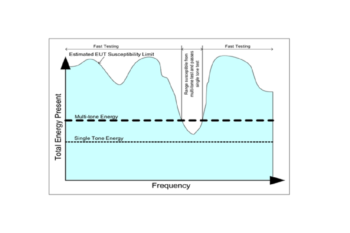
Testing can proceed at record speed once a determination of how many tones can be used and in what groups or sets. For each dwell period, the equipment under test (EUT) is exposed to a set of tones. If there is no EUT fault, the test continues. If a fault occurs, the user has the option to immediately investigate with a single tone to verify if the failure also exists when only a single test frequency is used or continue with the multi-tone test, making a note of where failures occurred. In the second case, after test completion, the failed frequency ranges would be rescanned with a single tone to see if the fault is unique to multi-tone testing or remains even when testing with a single frequency. Additional investigation and thresholding can also be performed at this time. If the EUT demonstrates sensitivity to multi-tones but not with a single tone, the EUT may be considered compliant with the test standard. The only downside is that one cannot reduce the test time at these frequencies.
Nevertheless, since large sections of frequency ranges can be scanned and tested quickly, the overall test time is still reduced dramatically. The graphical representation in Figure 6 captures this testing concept visually. Note that the test proceeds quickly from the lowest frequency up to a point when a fault is encountered. At this point, multi-tone testing is suspended, and the test reverts to single-tone conventional testing. In this hypothetical scenario, it is seen that the EUT passes the single tone testing, and multi-tone testing is resumed without further failures throughout the remaining frequency range.
The ability to test and demonstrate compliance, while significantly reducing test time, is possible using the multi-tone method. To meet the EMC standard, each and every tone during the test:
Immunity testing can be very time-consuming to perform. Often, tests take many hours, which constrains the throughput of a laboratory and limits the testing capacity for many facilities.
Historically, methods used to reduce the test time have focused on reducing the transition times (the time between the measurements of frequency steps), which unfortunately represents only a fraction of the total test time.
Multi-tone testing is a method designed to dramatically reduce test time by better using the required dwell time of the test. It is a process that adds multiple test frequencies (tones) to each test period (dwell time). Testing multiple frequencies simultaneously increases the test efficiency by a factor approximately equal to the number of tones used..
For example, if four tones were used, the test would be completed in about one-quarter of the normal time or four times faster a shown in Figure 7.
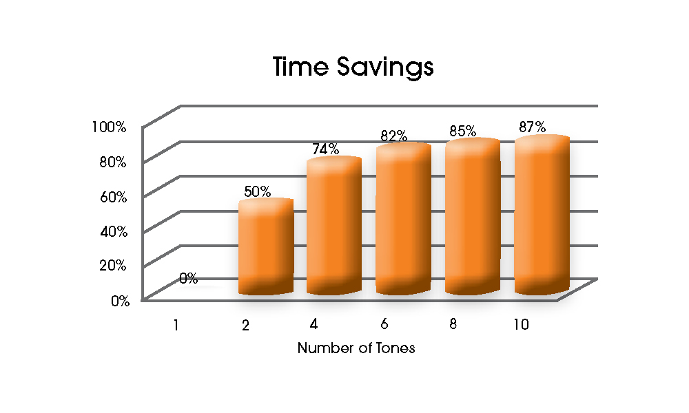
Figure 7: Percent time savings
Another benefit of using this technology is its ability to simulate real world threats, which are multi-tone in nature. Real world applications expose EUTs to more than one tone at a time. Conventional single-tone testing would never uncover susceptibility to these “actual” threats. Some equipment manufacturers have already experienced multi-tone induced EMC failures and have been using multi-tone testing to identify and correct product vulnerabilities. These real-world threats may not only be multi-tone in nature; there may be multiple concurrent and interactive threats present. An example would be EUT used in close proximity to a fully populated, multi-user 5G RF scenario.
.
The medical standard 60601-1-2 has listed many known threats and requires testing at elevated levels and altered modulations in these suspect bands. It also infers that product manufacturers should limit their liability by actively testing for any foreseeable threats. Standards containing more complex tests will likely follow suit.
EMC testing is standards driven. As more standards that require increasingly complex testing are released, demand for more efficient test methods will follow. This will drive the increased necessity for the use of digital signal generation and measurement techniques. The digital equipment is becoming more readily available, and less frequency limited. This type of testing will allow greater use in all application testing, from consumer products such as handheld and household devices to more complex assemblies associated with automotive, aerospace, and military industries.
160 Schoolhouse Rd.
Souderton PA 18964-9990 USA
215.723.8181
[email protected]
[email protected]
Contact Us
For an applications engineer call:
800.933.8181
For Customer Service, call:
215.723.0275
For Faxing Orders:
866.859.0582 (Orders Only, Please)
Privacy Policy
Terms of Use
Copyright ©2023 AR Inc.