Menu
Can you imagine the world without electronic devices? Today’s electronic gadgets, machines, and appliances have become an integral part of our lives. This is most apparent with recent developments in technology like drones, mobile internet, medical devices, Internet of Things (IoT), and autonomous vehicles. The result is a higher potential for harmful electromagnetic interference. This interference ranges from a small nuisance to complete product or system failures.
Historically, amplifier selection for Electromagnetic Compatibility (EMC) testing was based mainly on tribal knowledge and information scattered across the EMC industry. However, proper EMC amplifier selection is an important step in achieving required RF levels. It should be noted that quality and support are of equal importance as features when selecting an amplifier. Down-time from equipment failures often means test lab’s throughput slows, thus impacting the lab’s profitability and customer schedules. Additional considerations are numerous. It is important to properly understand the following in order to make a proper decision:
EMC can be defined as a system’s or equipment’s ability to operate in their intended environments without suffering unacceptable degradation or causing unintentional degradation due to electromagnetic spectrum interference. Threats to a system can be both naturally occurring and man-made and can be categorized into four main types of tests: Radiated Immunity, Radiated Emissions, Conducted Immunity, and Conducted Emissions. The limits and levels used for these tests are defined in various standards and adopted by various organizations. Products must meet the requirements outlined in these standards because public safety, among other things, relies on the products to perform as intended.
In many instances, the standard will drive the selection of the amplifier. In addition, the end-user will often have unique requirements. End-user considerations can be just as important as the industry standards. Standards commonly used in sectors such as military, aviation, automotive, and consumer are shown here:
Radiated Immunity
Radiated Emissions
Conducted Immunity
Conducted Emissions
In many instances, the standard will drive the selection of the amplifier. In addition, the end-user will often have unique requirements. End-user considerations can be just as important as the industry standards. Standards commonly used in sectors such as military, aviation, automotive, and consumer are shown here:
| Parameter | Definition | Relevance |
|---|---|---|
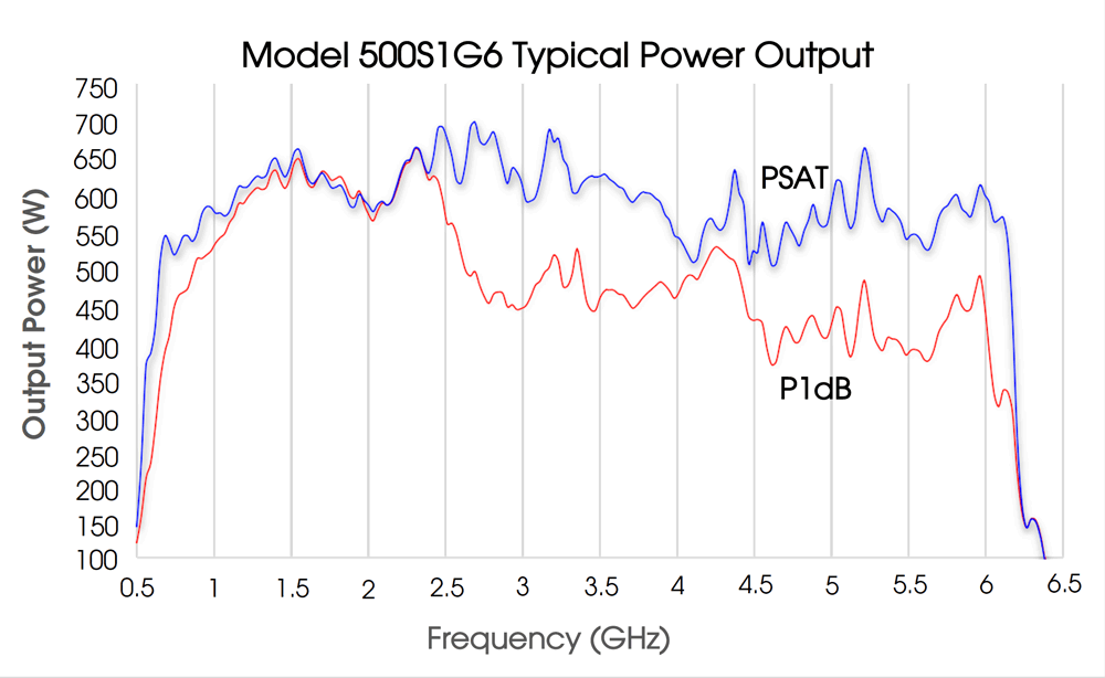
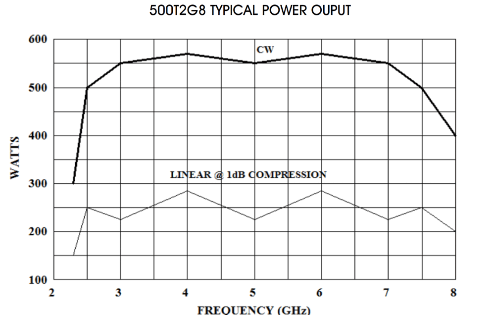
| Frequency Response | Instantaneous operational frequency band | Amplifiers are only specified to operate within this defined frequency band. Some solid state amps will operate just outside of the band with significant power reduction (Figure 1), whereas TWT amplifiers have a much harder cutoff due to waveguide (Figure 2). |
 | ||
 | ||
| Parameter | Definition | Relevance |
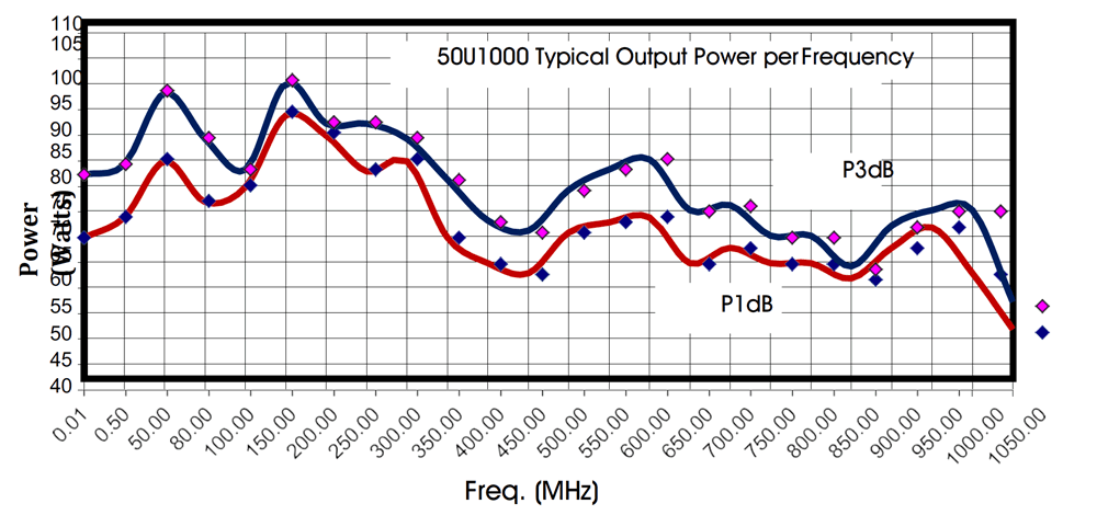
| Rated Output Power | The definition of ‘Rated Power’ varies by manufacturer. Some manufacturers will define it as the output power for a given input power across the operational bands others will define it as the amplifier’s saturated output power. There are additional definitions manufacturers will use. The key takeaway is to be cognizant of the definition used by the manufacturer in question. | It is important to remain cognizant of the manufacturer's definition as their definition of rated power may not satisfy your requirements. For example, if you require linear power and the manufacturer rates their amplifiers at something other than P1dB, you will want to size your amplifier according to the P1dB specification, rather than rated power. On the other hand, some manufacturers may specify rated power at P1dB, leaving extra power available for applications where linearity is not critical. |
| Power Output @ 1 dB Compression | Power generated by amp at the 1 dB compression point | Important power rating for applications where there are strict linearity requirements (IEC / EN). Can be considered the top-end of linear power. Amp saturation increases after P1dB. |
 | ||
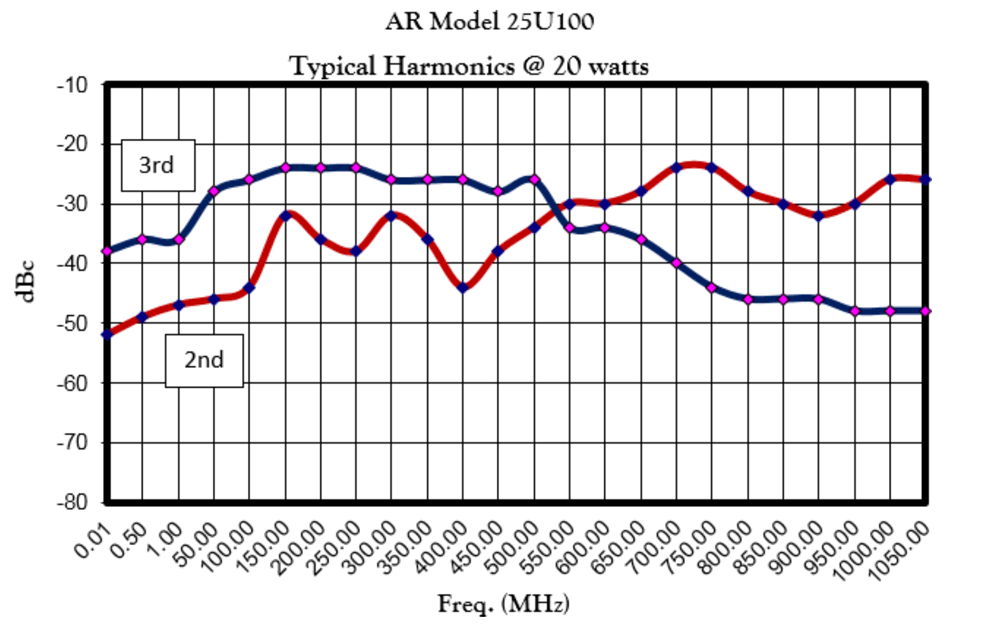
| Harmonic Distortion | The ratio of the sum of the powers of all harmonic components to the power of the fundamental frequency | Many test specifications require at least -6 dBc. It is important that the selected amplifier not contribute harmonic distortion more than what is required by the standard. |
 | ||
| Parameter | Definition | Relevance |
| Gain | The amplification factor, also called gain, is the extent to which an analog amplifier boosts the strength of a signal. Amplification factors are usually expressed in terms of power. | Many amplifier factors result from an amplifier’s gain, such as output power, size, and the power required to operate that amplifier. Gain is called S21 using S-parameter terminology |
| Flatness | This specifies how much the amplifier's gain can vary over the specified frequency range. | Variations in the flatness of the amplifier's gain can cause distortion of distort signals passing through the amplifier. |
| Efficiency | The ratio between the power of the output and total power consumption | Although Class A amplifiers are inherently less efficient than other amp classes, design techniques can improve amplifier efficiency. Highly efficient amplifiers are smaller and require less input power than other amplifiers with equivalent rated output power. |
| Pulse Capabilities | Limitations on Pulse Width, Pulse Rate, and Duty Cycle | Pulsed SSPAs and TWTs produce higher-peak power than-CW power but are limited in how much RF can be passed through the amplifier. |
| Modulation (AM, FM, PM) Performance | A variation to the properties of a periodic signal. | While there are a multitude of types of RF modulations used in today’s world, there a few specific modulations used by EMC test standards to approximate real-world threats, such as pulse modulation (PM) and amplitude modulation (AM). It is imperative that the amplifier used in testing be able to faithfully reproduce the required modulation without altering or adding extraneous distortion. |
| Mismatch Tolerance | Ability of an amplifier to handle un-matched loads and thus varying amounts of reflected power | In EMC applications, especially at lower frequencies, transducers (antennas / clamps / etc.) can be a very poor match to 50 Ohms. Field reflections / standing waves can cause significant reflected power as well. During tests, it is important to continue to deliver forward power and protect the amp from reflected power damage. |
How much input power is required to achieve full-rated output power is a common concern when choosing an amplifier. Some manufacturers have specified input of 1 milliW. However, that is not the case for every manufacturer, so it is important to verify. In these cases, while the rated input power is defined as 1 milliW, most amplifiers provide rated output power with less than 1 milliW input. This output power is because the specified value will often have built-in conservatism. Pay close attention, though, to an amplifier’s maximum input. It varies by vendor and possibly by model family.
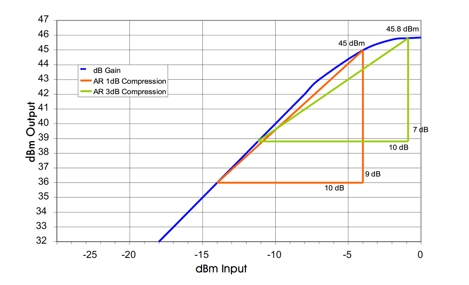
The input signal strength has a profound effect on the amplified output signal. It determines the operating region and, thus, the degree to which the amplifier output is compressed. Ideally, an amplifier will simply amplify the input signal without adding any additional signals or artifacts. Unless operated in the extreme linear region, amplifiers will distort the input to some degree. The extent to which the amplifier affects the input signal is a function of the output compression. The higher the amplitude of the input signal, the risk of output compression increases. At the 1dB compression point there may be a slight flattening at the top and bottom of a CW sine wave signal. As the amplifier is driven further into saturation, additional distortion will become apparent and eventually the CW input signal will approach a square wave output (See Figure 5). The 1 dB and 3 dB compression points are further shown in Figure 6.

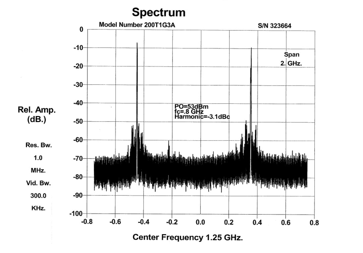
Distortion creates new unwanted signals at frequencies not present at the amplifier’s input, as observed in the frequency domain with a spectrum analyzer. Figure 7 shows the effect of driving a TWT amplifier into saturation. This figure shows the harmonic having only a slightly lower amplitude compared to the fundamental signal. This situation causes unnecessary problems for the test engineer. Under this scenario, if the EUT fails during radiated immunity testing, the test engineer will not know if the failure’s cause was due to the fundamental or the harmonic. To further complicate matters, if additional harmonics have high amplitudes, the test engineer must evaluate all harmonics to determine the failure’s cause. It is also possible that neither the fundamental nor a single harmonic causes a failure, but rather a combination of the fundamental and harmonic(s). The most commonly used power meters and field probes themselves are wideband measurement devices that will display the total energy across the entire band, fundamental, harmonics, and spurious; this can make measuring the amplifier output power or generated field additionally challenging.
EMC amplifiers range in types, such as Solid State, TWT, CW, Pulse, and their class of operation – Class A and Class AB.
Class A and Class AB amplifiers both have their strengths and weaknesses. Class A amplifiers are the most robust. They provide the highest levels of mismatch tolerance which is needed when significant RF levels reflect into the amplifier, a common effect with many EMC antennas and other transducers. Additionally, linearity and harmonic distortion are much better with Class A amplifiers compared to other amplifier classes.
Class AB amplifiers have their own benefits. Generally, the cost of the amplifier is less than Class A amplifiers. The physical size of these amplifiers is also generally smaller. These amplifiers are much better suited for use with matched loads. Read AR’s Importance of Mismatch Tolerance for Amplifiers Used in Susceptibility Testing to learn more.
Shown in the table below is a summary of the differences between Class A and Class AB amplifiers.
| Characteristic | Class A Amplifier | Class AB Amplifier |
|---|---|---|
| Output distortion | Low distortion, highest Linearity | Higher distortion, poor Linearity |
| Cost | More expensive | Less expensive |
| Ruggedness | Amplifier will safely operate without damage regardless of load mismatch | Output limits are generally used to protect the amplifier when operated beyond a stated level of mismatch |
| Size/Weight | Larger/Heavier | Smaller/Lighter |
| Construction | More components required to share the heat load | Less components required to share the heat load |
| AC power to RF power efficiency | Less efficient | More efficient |
| Bias Scheme | Output current flows for 360° of the input signal | Output current flows somewhere between 180° and 360° of the input signal |
For years, when discussing microwave, high field-strength electromagnetic compatibility (EMC) radiated susceptibility testing, Traveling Wave Tube Amplifiers (TWT Amplifiers or TWTAs) were the only choice for wide frequency coverage and power. TWTs are lower-cost solutions, in most cases, but they do have drawbacks. Their unique properties allow them to be used in a pulsed mode, which can lower the total required average power and maximize their peak power, thus, reducing cost further. However, TWTs produce high harmonics, have a greater noise floor, longer purchase lead times, longer repair times, and lower reliability than solid state amplifiers. Some advanced TWTs combine multiple tubes together to reduce harmonic content and increase total power. Another solution to reduce harmonics is to use filters on the amplifier output. It is important to remember that there are always losses associated with filters that must be considered for amplifier power sizing. The VSWR associated with the filters is another consideration, which can cause amplifier foldback.
The difficulties associated with pulse TWT amplifiers can be mitigated with a desirable alternative. Solid state pulse amplifiers offer high-power RF levels that rival those of TWTs. Modern solid state pulse amplifiers include various frequency ranges and output power levels to meet several standards and user requirements. These solid state pulse amplifiers offer higher reliability, better mismatch tolerance, much better harmonic distortion, and better MTBF (Mean Time Between Failure) than TWTs.
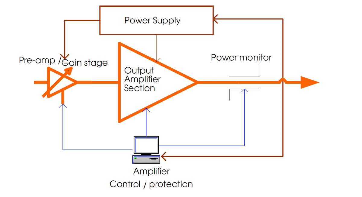
If a single band amplifier is not available over the desired frequency band, a dual band amplifier may be an attractive solution. A dual band amplifier consists of two amplifiers combined into one “box” with a single I/O interface, RF input and output, and two bandwidths equivalent to the two amplifiers it replaced. This approach simplifies the test setup.
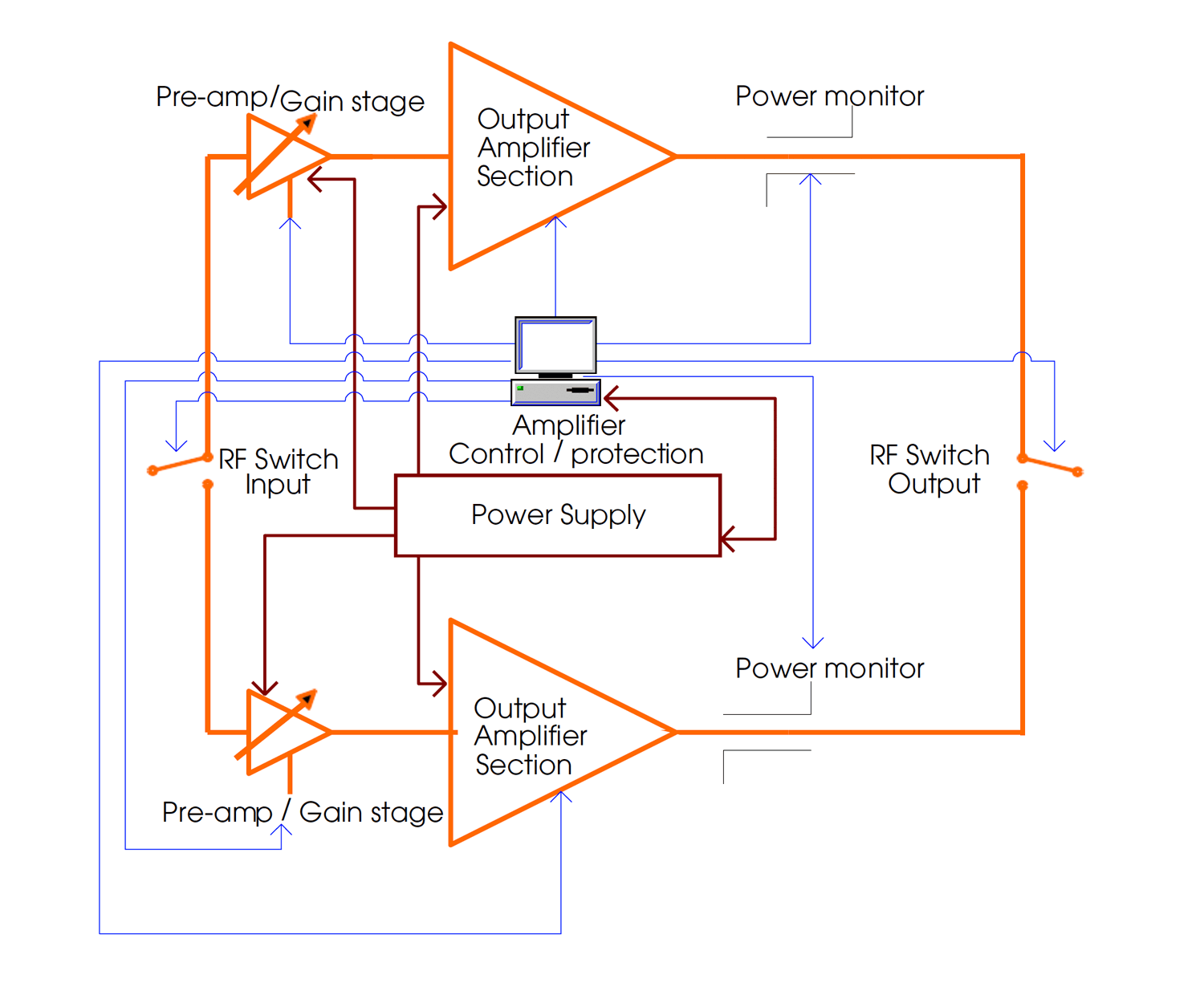
While the system seems simplified on the surface, a closer look within the “box” reveals a different story. While the two amplifier modules in a dual-band amplifier may share a common power supply, the overall system is complicated because it now consists of not one but two complex amplifier modules.
Furthermore, additional RF switching, cabling, and connectors are required, which will adversely affect both amplifier’s RF output. The additional components add insertion loss that may not present a problem at lower frequencies but can account for significant losses at higher frequencies. In addition, simultaneous signal generation across the entire band is impossible due to the required switching from one frequency band to the other.
Figure 10 and Figure 11 show the schematic differences between a single band and dual band amplifier, respectively.
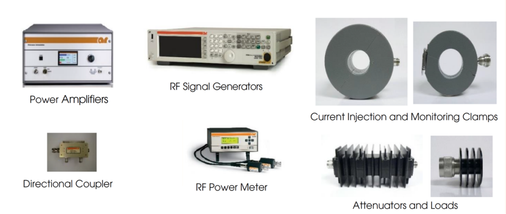
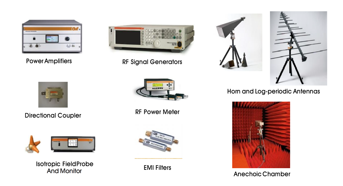
An often overlooked important part of an EMC test setup are the accessories. The cost and time associated with EMC testing warrants the use of high quality accessories. AR offers all the accessories needed to round out your system. This includes a family of antennas that operate up to 50 GHz and handle up to 20 kW. AR’s in-house antenna designers and experienced EMC design engineers have collaborated over the years to develop antennas that provide very attractive alternatives to traditional antenna designs. Examples include the models Radiant Arrow, ATT Pyramidal Log Period and AA series amplifier antenna products.
AR offers these accessories, with an experienced sales and engineering organization available to offer customers the best solution. Figure 12 and Figure 13 are examples of accessories used in radiated and conducted RF immunity test setups, respectively.
The transistors used in the amplifier are a main component of the amplifier. They can provide hints about the design and provide you with another data point in your purchasing decision. Different transistor technologies have been used throughout the years, including LDMOS, GaAs and GaN, among many others. While each technology poses various inherent pros and cons, GaN technology has become more prevalent in today’s marketplace. The benefit of GaN is greater power density than other technologies, which translates into higher power amplifiers and smaller overall packages compared to similarly powered amplifiers. Benefits like these are especially important in EMC applications as increased power is paramount for testing.
Almost always forgotten is the importance of product regulatory compliance. It is crucial for amplifiers to undergo safety, EMC, and hazardous substance evaluations. Not all amplifier manufacturers have made a commitment to global regulatory compliance. Because of this, some manufacturers are not able to distribute their product to certain regions of the world. Even in regions that don’t require such compliance, it is important to meet these requirements on all products in order to reduce potential harm to users and the environment. Independent third-party laboratories are often favored to evaluate products to international safety and EMC test standards, so there is no question about the validity of compliance compared to those manufacturers who choose to perform in-house evaluations.
If planning to use multiple signals/tones or complex waveforms to speed up testing and better represent real-world threats, a single broadband amplifier is the most appropriate choice versus a multiband amplifier or multiple amplifiers. A broadband amplifier can amplify all the signals simultaneously whereas a multiband amplifier may require multiple inputs and outputs. To learn more about Multi-Tone testing, read AR’s Multi-Tone: Testing, Theory and Practice.
There are many factors to consider when selecting an amplifier. Proper EMC amplifier selection is an important step in achieving required RF levels for the multitude of applications that exist today. To keep harmful interferences happening between military, automotive, medical devices, or even just the common household electronic devices; the necessary standards have been put in place. Once the standard at which the device needs to be tested against is determined, it is important to consider these other important factors during the amplifier selection process.
Need help selecting the right amplifier? AR’s Applications engineers have years of amplifier experience in areas such as EMC, wireless component R&D testing, and more. We are happy to discuss your requirements and assist you in selecting the right amplifier for your specific purpose. If you need assistance, please feel free to call at 215-723-8181.
160 Schoolhouse Rd.
Souderton PA 18964-9990 USA
215.723.8181
[email protected]
[email protected]
Contact Us
For an applications engineer call:
800.933.8181
For Customer Service, call:
215.723.0275
For Faxing Orders:
866.859.0582 (Orders Only, Please)
Privacy Policy
Terms of Use
Copyright ©2023 AR Inc.