The foundation for consistent and meaningful conducted immunity testing comes from defining the appropriate combination of amplification, injection device, and test set-up. RF conducted immunity (CI) is the test method and standard that substitutes for radiated immunity (RI) testing at lower frequencies. Due to antenna size, near field and grounding interactions, RI testing at lower frequencies is inherently problematic. Susceptibility to radiated energy at lower frequencies is more likely to find ingress on the equipment input/output lines; consequently, CI methods and standards were developed that replicate these radiated fields that would couple onto equipment cabling. Defining the system components is critical, considering and applying the correct method accordingly will result in dependable CI testing.
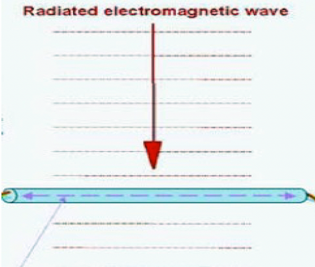
Any conductor can act as an antenna and allow energy to be induced upon it. To do so, it must be resonant at that given frequency. The free space impedance of a plane wave is approximately 370 Ω. An effective antenna, or a test cable acting as an antenna must transform this impedance to induce a current on to its conductor. Antenna impedance varies from approximately 73 Ω for 1/4 wave stub to 280 Ω for a folded dipole. (See Figure 1). Therefore, test methods have been established with levels based on lower impedance values, namely 50 and 150 Ω. Currents induced on multiple conductors may not be balanced. That is to say, the level and phase are not equal. All CI injection methods, however, are common-mode or equal level/phase on all conductors.
| ½ wave dipole | 70 Ω |
| ¼ wave stub | 50 Ω |
| Full Wave Loop | 100 Ω |
| Folded dipole | 280 Ω |
| Inefficient antenna | Z unknown |
There are four different methods that can be used to inject currents onto test cables. These methods include: Coupling/Decoupling Network (CDN), Bulk Current Injection (BCI), Electromagnetic Clamp (EM), and Tubular Wave Clamp (TWC), and Direct Interjection.
Coupling/Decoupling Network (CDN) The CDN device shown in Figure 2 uses passive components to inject the test signal onto the test cable conductor(s).
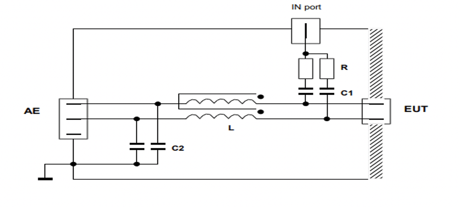
Isolation to auxiliary equipment (AE), fixed impedance (150 Ω), and low required injection level are the main advantages of the CDN method. Terminating to a fixed impedance permits a stable test level across the test frequency band regardless of the cable’s natural resonance. Some disadvantages of this method include the need for many different types of CDNs to match the test cable connector as well as the number of conductors, and current requirements. Serial communication through the AE low pass filter may also be degraded.
Bulk Current Injection (BCI)
The BCI device shown in Figure 3 uses inductive coupling to inject the test signal on to the test cable conductor(s).
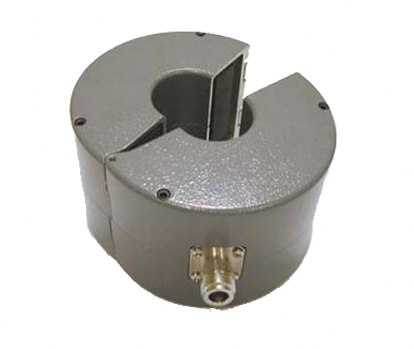
This method requires only one device to apply test levels to any cable assuming the cable fits the inside diameter. Probe frequency range, loss, and power rating must also be considered. This method, unlike the CDN, does not terminate to a fixed impedance. A cable will have a natural resonate impedance that will vary from near zero to many MΩ resulting in a widely varied induced current over the test frequency. Care must be exercised so as not to over test. However, as noted above, unless the cable acts as an antenna, radiated energy will not be efficiently induced. Therefore, the fact that a fixed test level across a frequency band is applied should not be a significant concern. Test levels are more accurately applied when the resonance approximates antenna impedances.
Electromagnetic Clamp (EM) and Tubular wave Clamp (TWC)
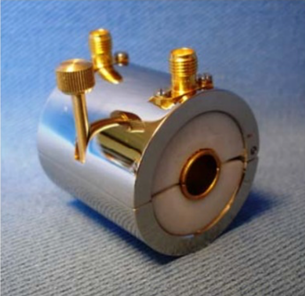
Like the BCI, these devices use inductive coupling to apply the test signal onto the test cable conductor(s). The same characteristics of a BCI apply, however, they also provide capacitive coupling (See Figures 4 & 5). Because of this, the frequency range is extended to higher frequencies.

Direct Injection
Direct Injection is the simplest method of current/voltage injection onto test cables. Resistor(s) and capacitor(s) are tied directly to the conductor(s). Although this is the simplest method, it can also be the most tedious to apply, as it requires cutting any insulation and making good electrical contact with all conductors (See Figure 6).
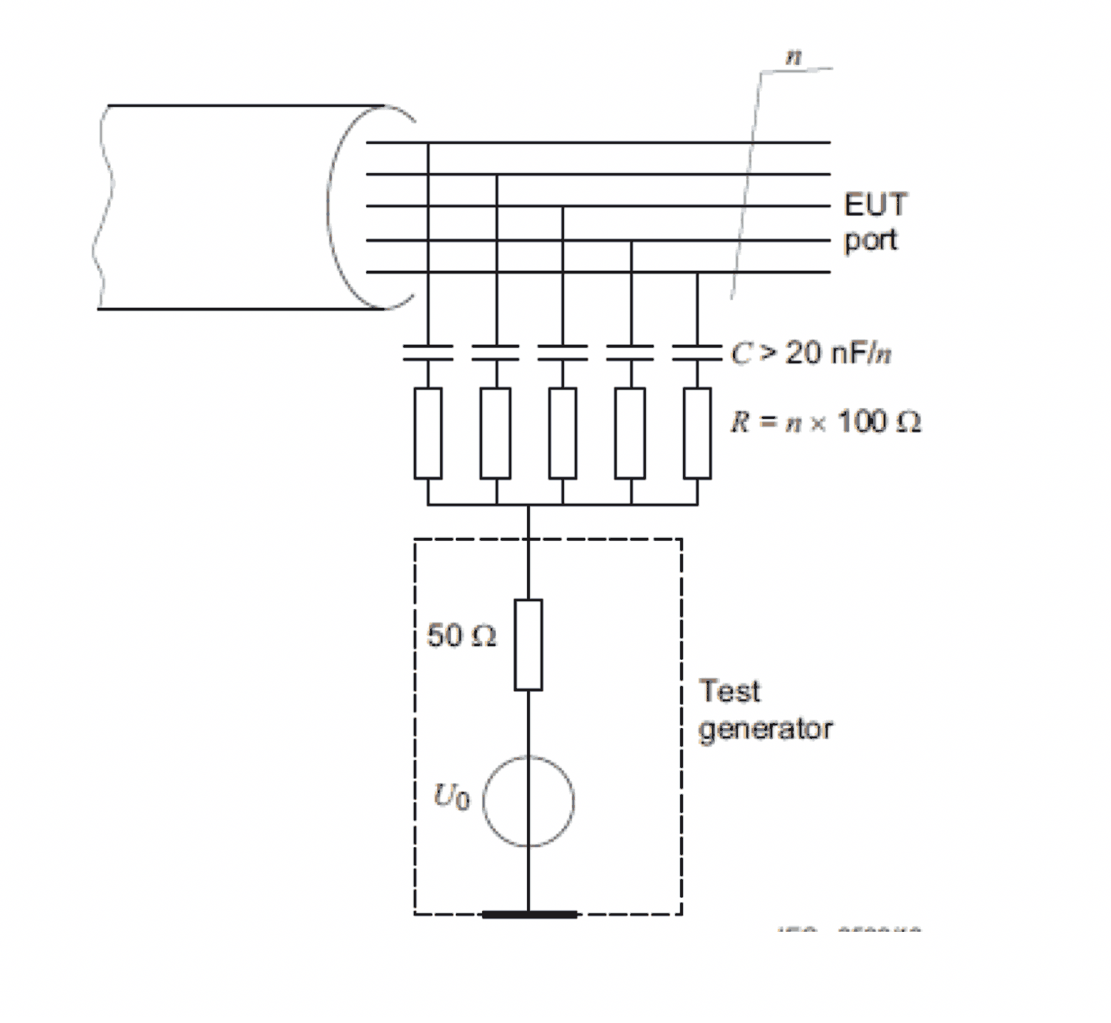
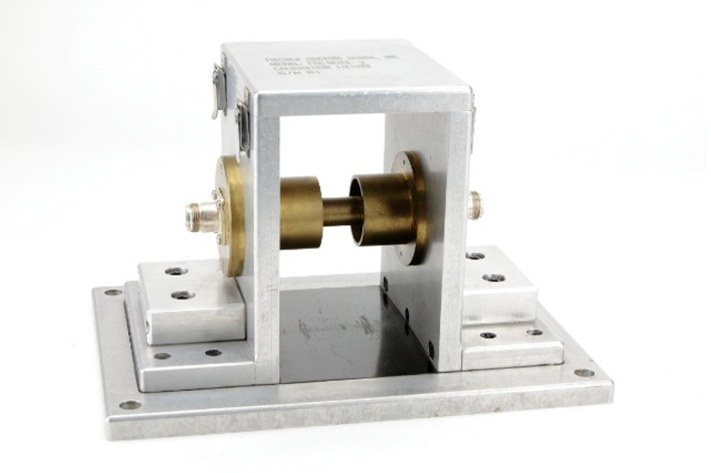
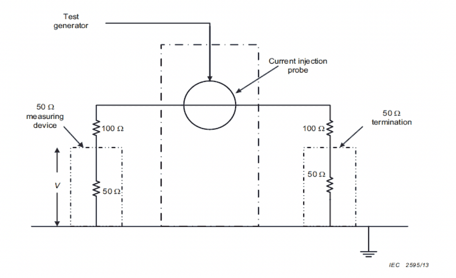
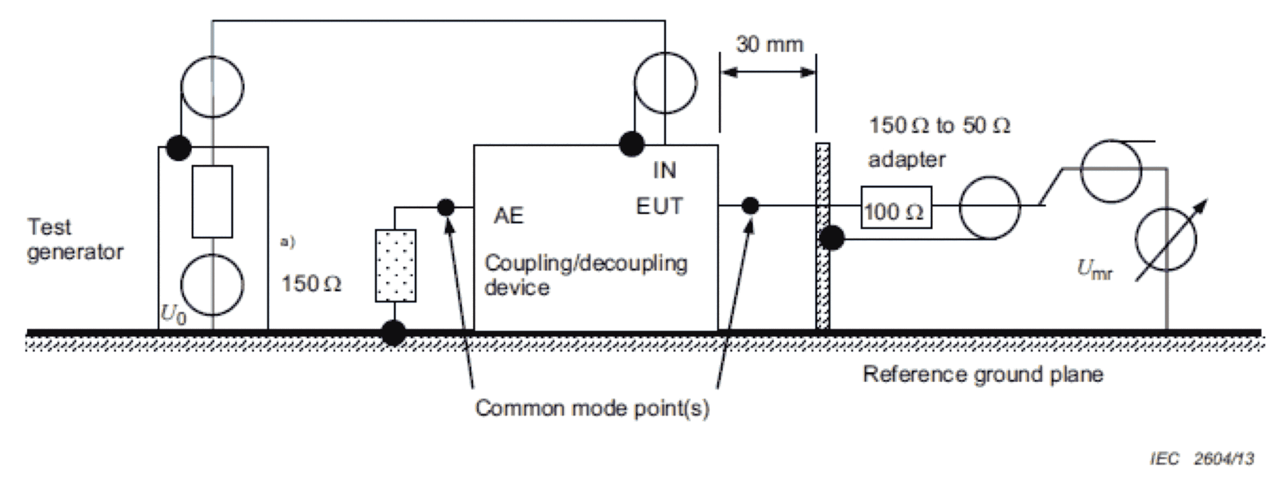
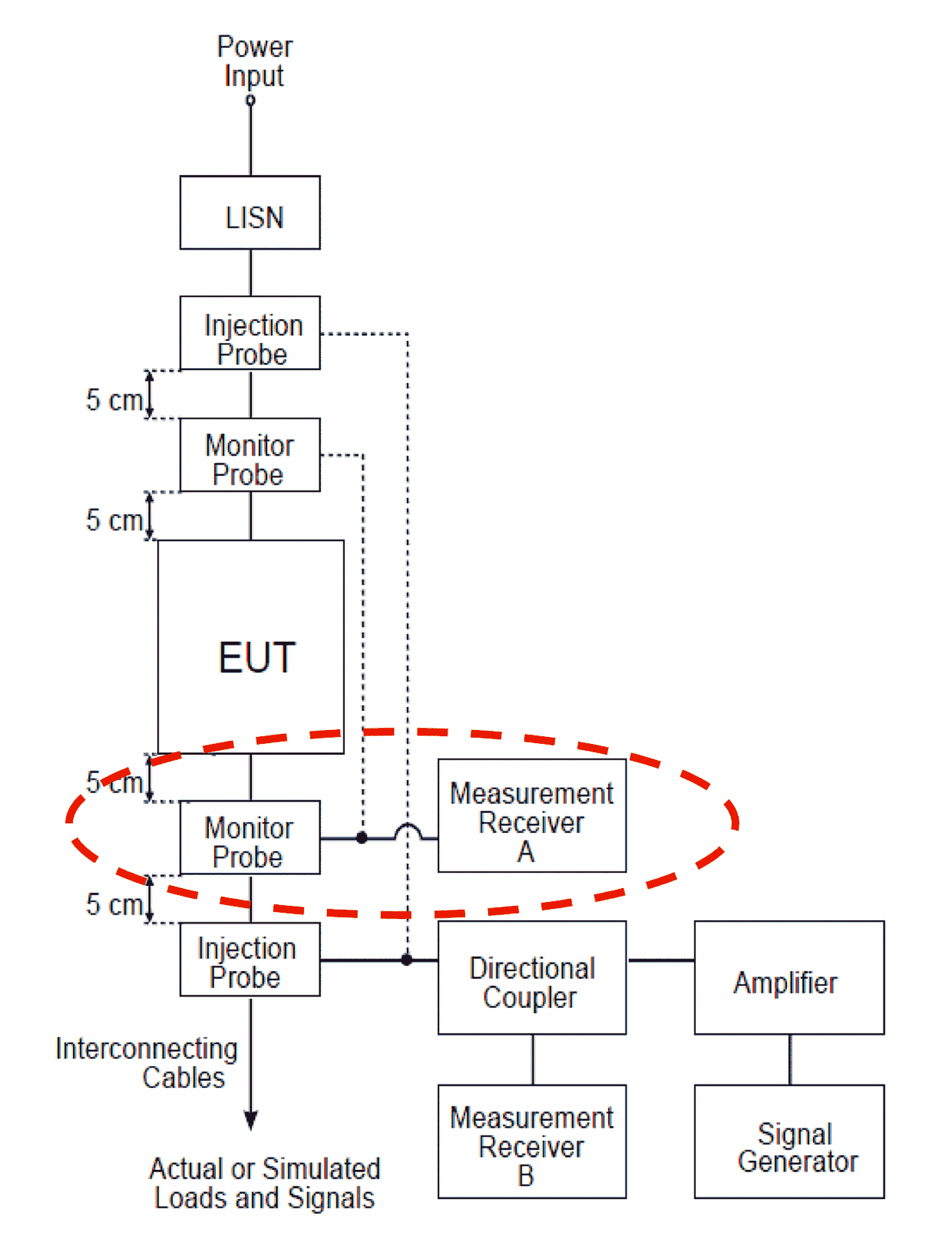
Due to the potentially high variability in test cable impedance, a calibration must be performed to determine the proper test level according to the test standard being used. Calibration is performed at a fixed impedance, either 50 or 150 Ω, depending on the standard. BCI, EM, and TWC clamps require a calibration fixture. As shown in Figure 7, the calibration clamp is fitted onto the jig over the single conductor. One side of the jig is terminated, and the other goes to the measurement device. In Figure 8, the forward power is recorded across the frequency band as power is adjusted to meet the required test levels. CDN calibration and IEC61000-4-6 are similar except that the termination impedance is always 150 Ω (See Figure 9).
Like RI testing, CI testing is performed using substitution or closed loop methods. The substitution method uses the recorded drive level from calibration to ‘playback’ the test level. Monitoring should be done to ensure an over-test condition will not occur (See Figure 10). Closed loop method actively monitors the current or voltage on the test cable.
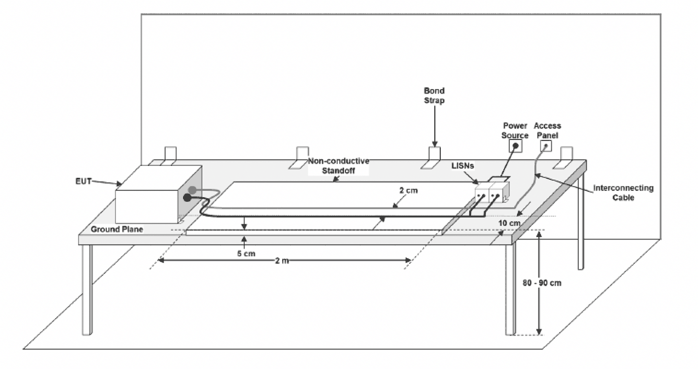
The table on which the cable and or equipment under test are placed is a critical consideration as well (See Figure 11). The test standard used gives specific guidance on the recommended configuration.
Defining the system components is critical as the appropriate combination of amplification, injection device, and test set-up varies widely. Understanding the foundations is important for consistent and meaningful CI testing. Conducted immunity testing is intended to replicate radiated immunity testing at low frequencies. Be sure to review the requirements defined by the standard you are testing to and make sure an appropriate calibration is performed. Always consider the objective of your test and apply the correct method accordingly.
160 Schoolhouse Rd.
Souderton PA 18964-9990 USA
215.723.8181
[email protected]
[email protected]
Contact Us
For an applications engineer call:
800.933.8181
For Customer Service, call:
215.723.0275
For Faxing Orders:
866.859.0582 (Orders Only, Please)
Privacy Policy
Terms of Use
Transparency in Coverage (TCR)
Copyright ©2023 AR Inc.