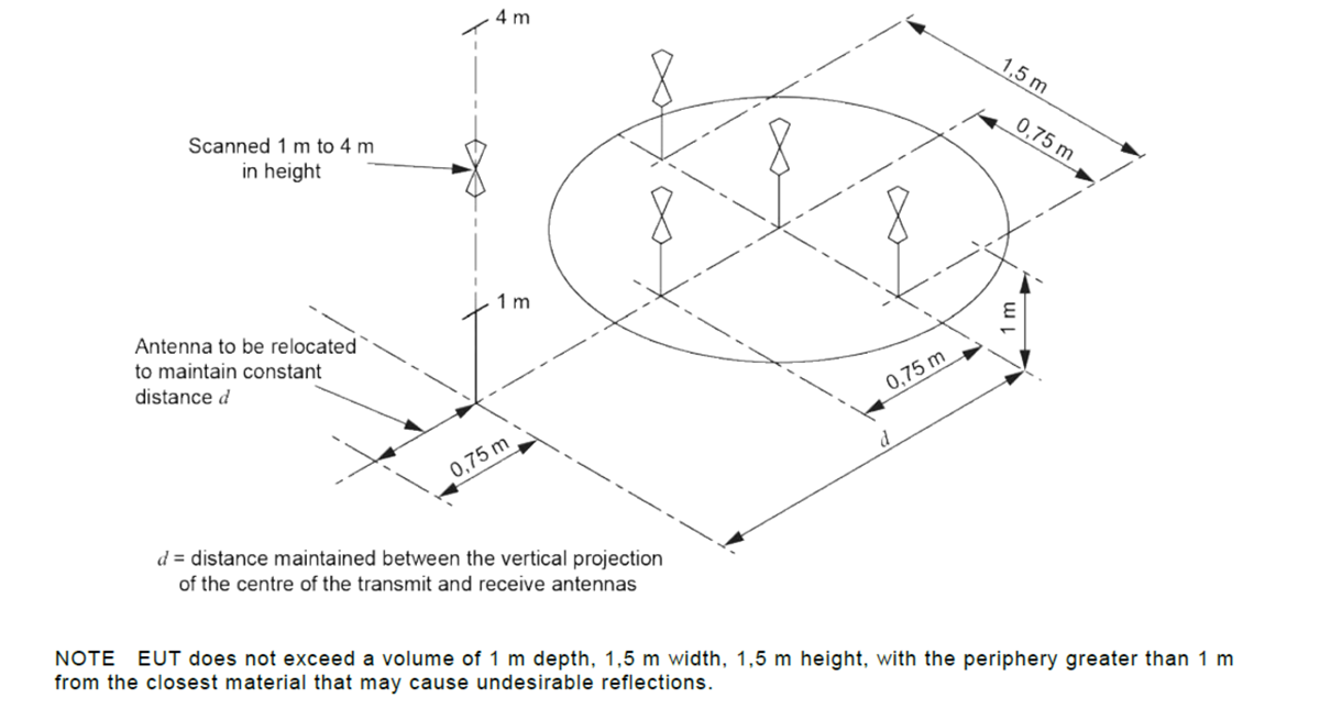
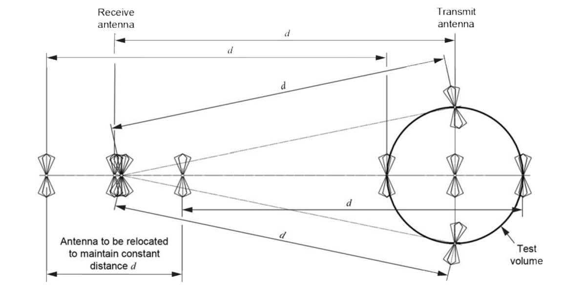
Normalized Site Attenuation (NSA) is utilized to determine the suitability of a test site, whether the test site is an Open Area Test Site (OATS), a semi-anechoic shielded enclosure chamber (SAC), or a fully anechoic room (FAR). The requirements for NSA are defined in CISPR 16-1-4 and ANSI C63.4, which each have very similar requirements. Site VSWR measurements for above 1 GHz site characterization will be discussed in a future resource.
NSA is the measurement of the loss between two antennas, which is then compared to defined values for an ideal test site. The deviation between the test site’s NSA and the NSA for an ideal test site is caused by imperfections in the test site, such as in the ground plane configuration on an OATS or in the absorber configuration for a chamber or room.
The typical frequency range of NSA measurements and validation is from 30 MHz to 1 GHz but can be expanded in certain cases, depending on test standard applicability. These measurements are performed for a test volume that defines the largest potential EUT size of the test site.
For a three (3) meter test site, guidance and requirements are given in the applicable emissions testing standards. For example, EN 55032 / CISPR 32 state that the maximum width of the EUT shall be within the test volume defined during NSA measurements. So, if the maximum volume of the test samples to be tested is defined as 1 meter by 1 meter by 1 meter, the NSA can be performed for that test volume. However, if a test sample exceeds the NSA volume, then NSA must be performed for that specified volume (or larger).
EN 55011 / CISPR 11 defines the sizes of equipment. For a three-meter measurement, the EUT, either floor standing or tabletop, must fit within a cylindrical test volume of 1.2 meters in diameter by 1.5 meters above the ground plane. Anything larger, including the cables, must be tested at 10 meters, provided the test site meets NSA requirements.
For the FCC (United States) and ISED (Canada), the guidance for different types of test sites and their testable volumes is given in ANSI C63.4:2014.
For a test site, the NSA is performed once per laboratory-defined calibration cycle, which is generally on an annual basis. Additional NSA measurements should be made if there are changes to the test site, such as, but are not limited to:
Discrete frequency measurements are made and compared to tables listed in either CISPR 16-1-4 or ANSI C63.4. Swept frequency measurements can be made and require broadband antennas.
It should be noted that the antennas used during NSA measurements are not required to be the same antennas utilized during testing. The purpose of these measurements is to qualify the physical test site for attenuation and not the antennas. For clarification of the antennas used, the responsible body should refer to the applicable test standard, version-specific, for the subject tests and measurement.
Initially, two (2) antennas are set up on the test site in the appropriate geometry. The first measurement, VDirect, is measured with the transmit and receive coaxial cables disconnected from their respective antennas and connected directly with an adapter, and the signal source set to a value (V1). This measurement gives a direct source-toreceived measurement, of which all other measurements are based. Care should be taken to ensure that the cables and adapters used are appropriate for the frequency being measured. The second measurement (VSite) is taken with the cables connected to the antennas and the maximum signal measured by raising and lowering the receiving antenna. Note that the signal source (V1) continuously remains constant.

The measurements are repeated for multiple positions and each polarity (horizontal and vertical) of the antennas. For test sites where larger EUTs are measured, multiple antenna locations are used to ensure that the usable volume of the test site meets NSA requirements.


Once the measurement is recorded, the NSA is calculated via the following equations
Where:
Note: the equation above is derived from ANSI C63.4. CISPR 16-1-4 equations are the same with the variables having slightly different abbreviations
Once the calculations are complete for the attenuation, the result is then compared to the theoretical NSA listed in either ANSI C63.4 or CISPR 16-1-4. If the result is within ±4 dB of the theoretical NSA, then the test site is deemed to comply with the Normalized Site Attenuation requirements for that specific position, frequency, and polarization. If not, the source of the error must be investigated, and the process shall be repeated.
For a weather-protected OATS or a shielded anechoic chamber, a single measurement height is insufficient given the possibility of reflections from construction materials and trapped moisture in the walls of the enclosure. For these scenarios, a ‘test volume’ must be defined, which is the volume of the largest potential EUT tested and rotated about its center. Multiple heights are also required to ensure that the roof of the weather-protected OATS or top of the SAC does not affect the NSA.
Near field effects can be observed when measuring at test distances of less than 5 meters in a Fully Anechoic Room (FAR). A Reference Site Method (RSM) accounts for those effects involving a biconical antenna at three (3) meters.
To account for the near-field effects, an additional factor, AAPR is subtracted from the initial attenuation calculation:
Where h is the height of the antennas and d is the distance between them. The reason for this increase is to suppress influence from the ground. The same suppression can be achieved by covering the coverage area with RF absorber material suitable down to 30 MHz.
Once the height is achieved, the measurement can be made by the equation:
Where the VDirect RS and VSite RS are the same measurements obtained above, just with the height increased as above stated.
For CISPR 25, the RSM method can be utilized for comparison to an Open Area Test Site, provided the OATS meets the requirements of CISPR 16-1-4 or ANSI C63.4. The challenge here is to have a laboratory with each of the two test environments for comparison (reference) measurements.
The above synopsis of Normalized Site Attenuation and Reference Site Method measurements indicates a challenging but important aspect of radiated emissions measurements on an OATS, SAC, or FAR. A compliant test site produces repeatable test results and instills confidence in both customers and test personnel. Amplifier Research offers turnkey solutions and systems, which can be accessed at http://www.ARWorld.US, or call our applications engineers at 800-933-8181.
ANSI C63.4 (2014), American National Standard for Methods of Measurement of Radio-Noise Emissions from Low-Voltage Electrical and Electronic Equipment in the Range of 9 kHz to 40 GHz
CISPR 16-1-4, Edition 4.0, International Standard, Specification for radio disturbance and immunity measuring apparatus and methods – Part 1-4: Radio disturbance and immunity measuring apparatus – Antennas and test sites for radiated disturbance measurements.
160 Schoolhouse Rd.
Souderton PA 18964-9990 USA
215.723.8181
[email protected]
[email protected]
Contact Us
For an applications engineer call:
800.933.8181
For Customer Service, call:
215.723.0275
For Faxing Orders:
866.859.0582 (Orders Only, Please)
Privacy Policy
Terms of Use
Transparency in Coverage (TCR)
Copyright ©2023 AR Inc.