Heterodyning, or the mixing of two radio frequency signals to produce new signals, particularly one at the sum F1+F2 and the other at the difference F1-F2, has been known since the earliest years of the 20th century. Edwin Armstrong’s super heterodyne receiver, invented in 1918, mixed the received signal with a local oscillator to produce a constant intermediate frequency (IF) that can be processed more simply than the original carrier frequency. This enabled the tremendous benefits of IF filtering and amplification which can be found in virtually all modern radio receivers. The consequences of unintentional frequency mixing likely first came to light in these early days of radio broadcasting. People observed that signals from two high-power broadcast stations could mix together on a rusty bolt, corroded rain gutter or other seemingly inert fixture to produce a signal at a new frequency, interfering with whatever service that was legitimately assigned to that frequency.
Passive Intermodulation (PIM) is a type of intermodulation distortion that can occur when two or more relatively high-power signals exist within a system. PIM arises from electrical nonlinearities within the system, which act as unintentional mixers. Nonlinearities can occur at loose connections, at contaminated or corroded metal surfaces, through ferromagnetic metals, and many other causes.
PIM is especially troublesome for systems in which receive signals and transmit signals share a common transmission path, such as a coaxial cable, coupler, or antenna. This is commonplace at cell sites, on communication satellites, and in wireless networks. Two high-power signals on different frequencies within the transmit band may mix to create an intermodulation product that falls within the receive band, leading to a reduced signal-to-noise ratio, increased bit error rate, and reduced quality of service. For instance, satellite to ground communication involves very high power signal transmission coupled with highly sensitive receivers. If precautions are not taken, the high-powered transmission signals can easily create PIM, and this distortion can mask sensitive receive bands.
The frequencies of the intermodulation products are integer linear combinations of the two transmit signal frequencies: Fpim = ± M*F1 ± N*F2. The quantity M+N is known as the “order” of the product. Examples of these products are:
| F1 + 2*F2 | 3rd Order |
| 3*F1 + 2*F2 | 5th Order |
| 4*F1 + 3*F2 | 7th Order |
| 2*F1 + 7*F2 | 9th Order |
PIM is by nature a non-linear phenomenon. PIM levels will generally increase disproportionately with the power level of F1 and F2. For example, a 3 dB increase in F1 and F2 may result in a 10 dB increase in the level of PIM. Also, the order of the intermodulation product is of importance. Third order products (±2*F1 ± F2 or ± F1 ± 2*F2) are generally the strongest and most likely to fall within a nearby receive band, with higher orders (5th, 7th, 9th …) being progressively weaker.
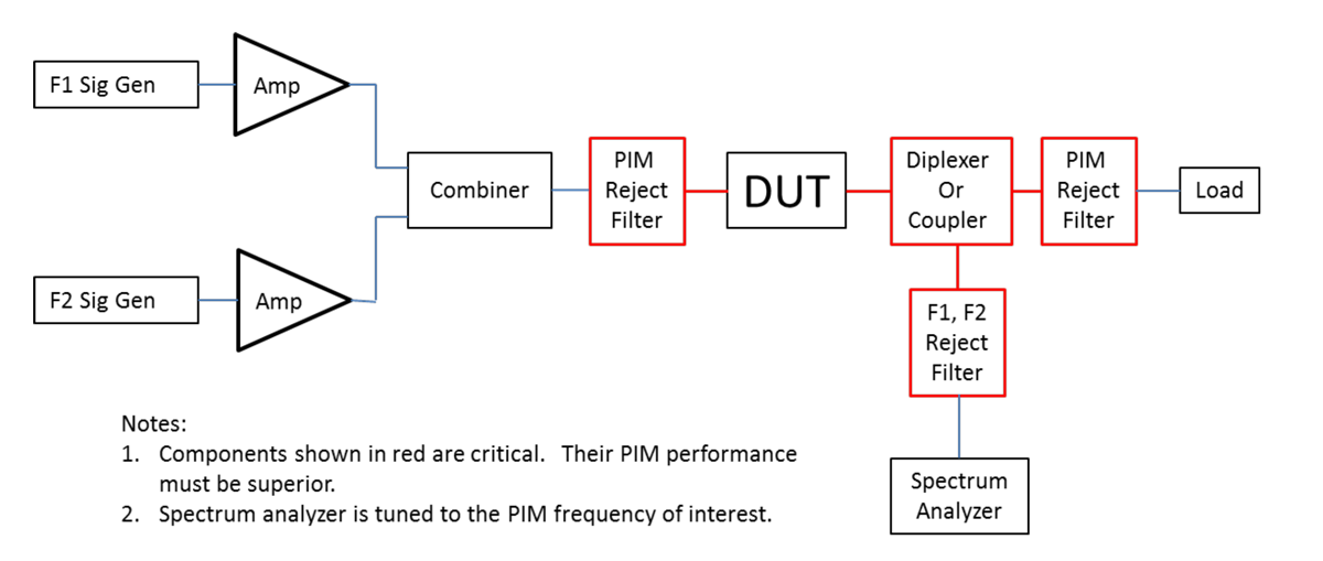
PIM can be minimized by utilizing proper design techniques; however, it is still best practice to verify PIM performance by test. A basic PIM test setup is shown in Figure 1.
This setup is appropriate for the test of a two-port component such as a cable or a filter. F1 and F2 are frequencies within the transmit band of the device under test (DUT). F1 and F2 are chosen such that their intermodulation product falls within the receive band of the DUT. PIM levels are generally given in dBm and are often very small, such as -100 dBm or even lower. That said, PIM requirements can vary widely and are highly dependent on the DUT and its application. Although Figure 1 represents a common PIM test setup, which could be used to test a 2-port DUT, more complex setups are often used. For example, setups may use more than two carriers and the carriers may be at different power levels. The diagram is also applicable to the PIM test of antennas, with an anechoic chamber replacing the load and its filter.

Assuring that the PIM test setup itself does not corrupt the PIM measurement can be a challenge. The test setup’s performance must be defined in the context of the test power levels, PIM order, and PIM performance requirement being tested. The test setup intends to introduce only F1 and F2 to the DUT. The filters labeled “PIM Reject Filter” function to pass F1 and F2 but strongly reject PIM products that fall within the band of interest, for example, the receive band. The filters, couplers, and interconnects all combined, in proximity to the DUT, must have better PIM performance than the DUT’s PIM requirement. This can be a design driver for the test setup and may require more advanced and costly fabrication techniques. Coaxial cables and connectors used in the setup are problematic; their PIM performance can degrade with use. Highly demanding PIM requirements may even preclude the use of coaxial connectors. High power loads can generate PIM and may need to be filtered. Long spools of cable are sometimes used for loads because their PIM performance is better than conventional loads. In the case of antennas, the anechoic chamber’s PIM performance must be better than the DUT requirements.
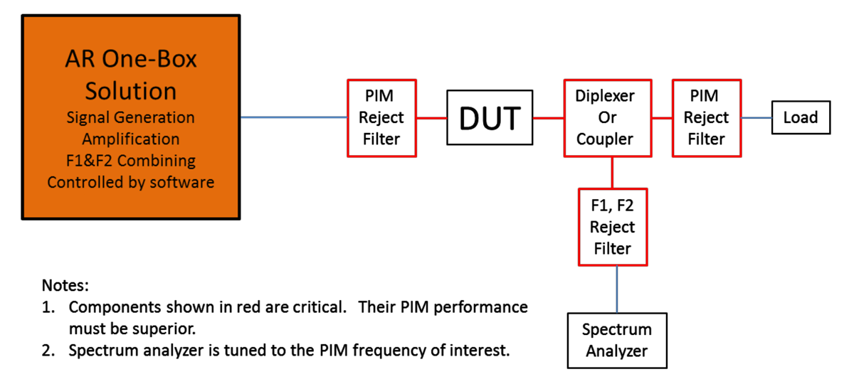
The above solutions to obtaining accurate measurements are tedious and complex, but AR can help you reduce your PIM test setup complexity by providing custom components and one-box solutions. These solutions can cover a wide frequency and power range to satisfy many PIM applications, including wireless, Bluetooth, L-Band, S-Band, and satellite communications. A conceptual example of what AR can provide is given in Figure 2.

Typically, separate amplifiers are used for F1 and F2. This is done to avoid intermodulation products produced inside the amplifier. However, AR has vast experience in limiting intermodulation and harmonic distortion from our amps. By providing this rejection at the amplifier, the complexity of the test setup and the demands on the “PIM Reject Filter” can be reduced, thus eliminating the need to use two amplifiers. This is an example of a possible solution that AR can provide.
Through a long history of designing systems and test equipment, AR can come to your assistance by using our expertise to help design and select these extra instruments and items to satisfy your specific PIM requirements for both pre-compliance and compliance testing.
160 Schoolhouse Rd.
Souderton PA 18964-9990 USA
215.723.8181
[email protected]
[email protected]
Contact Us
For an applications engineer call:
800.933.8181
For Customer Service, call:
215.723.0275
For Faxing Orders:
866.859.0582 (Orders Only, Please)
Privacy Policy
Terms of Use
Transparency in Coverage (TCR)
Copyright ©2023 AR Inc.