Menu
Today both commercial and military industries are more reliant than ever on electronics. In addition, the need to protect those electronics from potential threats has become even more vital. Threats like electromagnetic interference (EMI) and High-Altitude Electromagnetic Pulse (HEMP) have the ability to interrupt or even destroy the functionality of unprotected electronics. The military has long been aware of the effects of electromagnetic interference and has taken proper precautions to shield electronics, but in some cases, additional measures are required to ensure proper operation. Therefore, the military has, for a long time, often used shielded rooms to house their network and other equipment.
Furthermore, as the entire world is moving towards innovations backed by emerging technologies such as IoT (Internet of Things), Blockchain, Automation, AI (Artificial Intelligence), etc., the need for storing and protecting the proprietary information has become extremely critical. With the increased amount of electromagnetic pulse (EMP) and EMI threats, the shielding requirements have become more stringent and time-critical in testing facilities’ shielding effectiveness. The AR Model CL-105A/CL-106A, Shielded Enclosure Leak Detection System (SELDS), is an instrument for verifying shielded enclosures’ integrity. The SELDS method can be used at almost any stage of enclosure construction, but it is most accurate and efficient when used after the facility electromagnetic barrier is fully complete. SELDS can also be used to evaluate the shielding effectiveness of non-military and commercial applications— banks and financial institutes, data centers, research and medical hospitals, nuclear power plants, subways, submarine pipelines, telecomm base stations, etc.
Any closed box could be considered “shielded” to some extent—even a lunch box—but to achieve the level of shielding needed to meet the stringent requirements of standards such as MIL-STD-188/125-1 and MIL-STD-461G, an enclosure must be sealed to the extent that signal leakage is minimal. The primary purpose of the MIL-STD-188-125 Shielding Effectiveness (SE) test is to demonstrate the SE integrity of a shielded room/facility, conduit, and apertures Point-of-Entry (POE) as noted in Appendix C and SELDS survey IAW MIL-HDBK-423. The shielding effectiveness of the shielded barrier required for high-risk HEMP application is necessary to protect ground-based electronics with time-critical missions.
Part 1 of MIL-STD 188-125 “High-Altitude Electromagnetic Pulse Protection for Ground-Based Facilities Performing Critical, Time-Urgent Missions Part 1 Fixed Facilities” references the military handbook (MIL-HDBK-423) for Shielding Effectiveness (SE) integrity test methods. SELDS test method is an electromagnetic method for locating leaks in welded and brazed joints, including seams, patches, etc. During construction, the final SELDS test is accomplished when the barrier is complete, prior to the final acceptance test. Furthermore, the SELDS technique is frequently the basis of the built-in shield monitoring capability required by MIL-STD-188-125. So, the ideal EMI shielded room would be a metal box with no seams, openings, or ingress from cables. Still, unfortunately, that’s not possible due to the need for access to the equipment and military personnel inside. SE testing often identifies weaknesses in the shield, which are not visually detectable.
There are two characteristics that determine the electromagnetic shielding effectiveness of an enclosure:
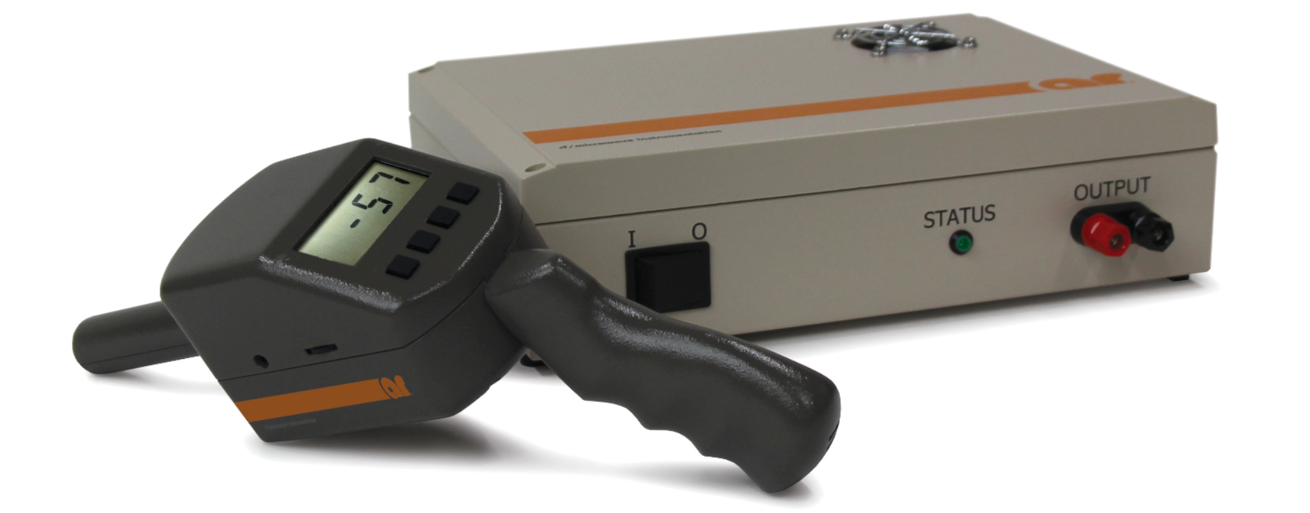
This application note will focus on the SELDS approach defined in the military handbook (MILHDBK- 423), to determine SE, using the AR rf/microwave instrumentation (AR) CL-105A/CL-106A, shown in Figure 1.

AR RF/Microwave Instrumentation has unveiled a Shielded Enclosure Leak Detection System (SELDS) for testing the electromagnetic shielding effectiveness of EMI enclosures. The new CL-105A/CL-106A detection system allows detection at the most likely points of degradation – the seams, doors and filters connections, in a convenient and hassle-free method. Discontinuities permitting RF leakage at welds, seams, corners, etc., can be detected and remedied to ensure that the finished enclosure is properly assembled.
The system consists of a Model CL-105A Transmitter, Model CL-106A Receiver, headphones and a rugged carrying case. The incredible sensitivity of the model CL-106A Receiver allows it to meet the most rigid MIL standards (e.g. MIL-STD-188/125) for shielded room acceptance. The system is designed to make relative shielding effectiveness measurements by passing a current along the surface of an EMI enclosure in order to sense the small magnetic fields formed where breaks in the EMI enclosure may occur.
The Model CL-105A Transmitter is used to generate an output signal (96kHz) which is connected to the EMI enclosure under test. This device has an auto-adjusting output that works with small, medium, and large EMI enclosures. The 96 kHz signal is low enough in amplitude to ensure that a relatively uniform RF current flow occurs on all sides of the enclosure. An LED indicator illuminates green when the Transmitter has adjusted the output to the optimum level for the connected EMI enclosure.
The Model CL-106A Receiver has high sensitivity (dynamic range:120dB) to detect the smallest of magnetic fields produced at breaks/discontinuities in the EMI enclosure under test. This unit autozeros and features an auditory output with a varying amplitude related to the shielding effectiveness. The auditory output is available through the built-in speaker or included headphones. A 4-digit, seven-segment display is provided to indicate relative shielding effectiveness measurement values in dB. In addition, a built-in LED light source provides illumination when used in dark environments.
The Model CL-105A/CL-106A system is comprised of two main parts; a Transmitter and a Receiver. The Transmitter is designed to drive a current through the skin of a shielded enclosure. The CW output signal has a frequency of 96kHz. The system is designed to drive very low impedances; thus, the Transmitter is operating as a current source. The output current is nominally 800mA RMS.
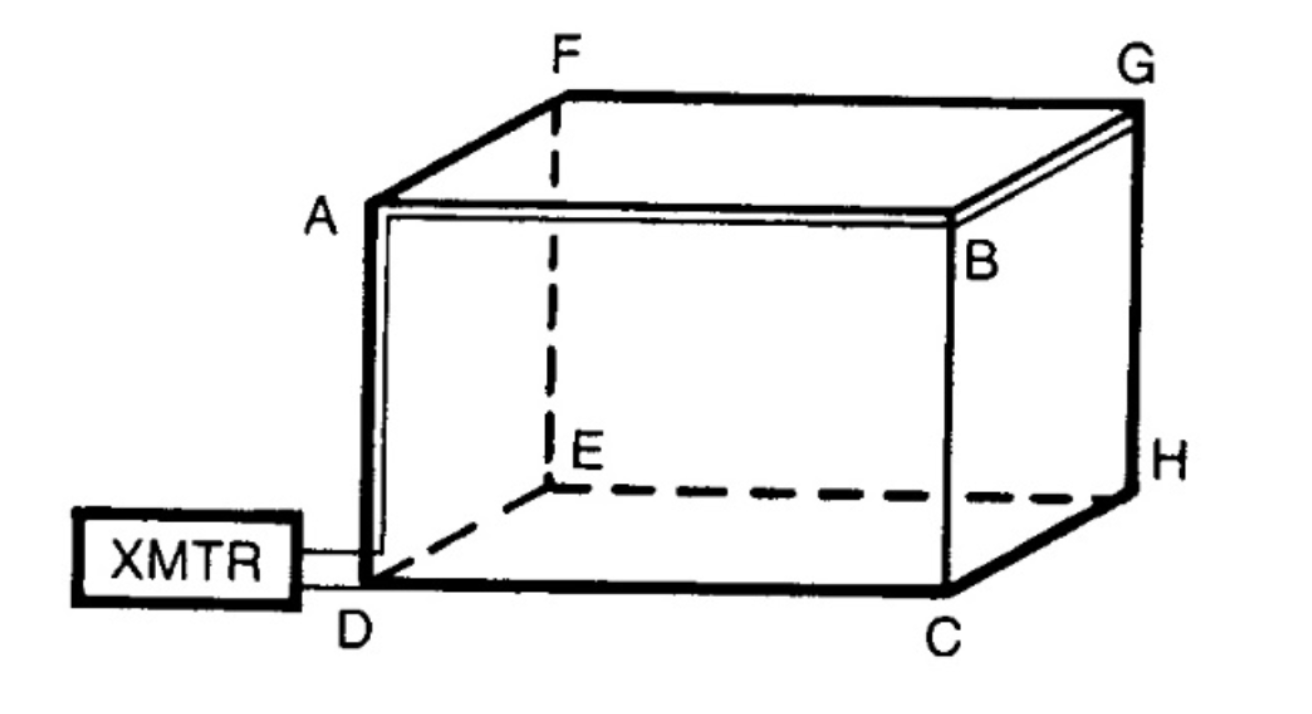
For normal tests, the Transmitter will be connected via feed wires to opposite corners of the enclosure exterior and will transmit an AC current across the metallic surface of the enclosure. The Receiver cannot detect the signal except at the points where the enclosure has openings or metallic discontinuities, which cause a small magnetic field to form. The unit is designed to detect small leakages within a larger contiguous surface, not for detecting intended openings (e.g., open chamber door, waveguide feedthrough). There will be a small magnetic field formed at any place in the enclosure with a small leak (e.g., a crack or seam gap). The Receiver is designed to detect these small magnetic fields. As the Receiver is moved along a seam and encounters this magnetic field, the display will indicate a relative decibel value when detecting a sufficient field level, dependent upon the Receiver sensitivity settings. An audible tone will increase in volume at higher value indications. The audible tone is not calibrated but is an indicator that simplifies chamber probing without requiring continuous observation of the display. If a poor seam or opening exists in the enclosure walls, a signal will be detected when scanning with the Receiver. Detected signals will cause the Receiver display to indicate larger values, indicating less shielding effectiveness. The unit of measure is Shielding Units (SU), a relative measurement from the calibration level set at AR’s factory. The system’s measured values allow identifying areas of potential RF leakage and decreased shielding effectiveness but cannot be directly converted to Shielding Effectiveness measurements obtained using other methods.
The indication of shielding effectiveness is directly related to each seam’s quality of workmanship, door seal, and filter connection. When the system is used to probe around these places, the maximum displayed value indication pinpoints the fault’s location, which may be, among other things, a loose bolt, bent panel, or corroded door facing. The data acquired by this system may be used as a guide for: (1) immediate corrective actions, (2) correlation for proof of performance test as a basis for future acceptance tests, or (3) enclosure profiling. Due to the high energy electromagnetic fields which surround each feed wire, a strong local effect is created, which may be detected by the Receiver along the path of the feed wire, and if this effect is not taken into account, the resulting readings near the feed wires could be misconstrued as indicating a faulty seam. Due to this effect, a second feed wire configuration is used in which the feed wires are placed in such a way as to be an approximate mirror image of the first configuration. Chamber probing is then repeated along the path of the original feed wire to confirm leakage points. The user familiar with attenuation scales on conventional RF measuring equipment should notice that the system is calibrated to indicate direct shielding effectiveness rather than field strength. Since an increase in received signal occurs when the shielding decreases, an increased signal causes the displayed value to decrease.
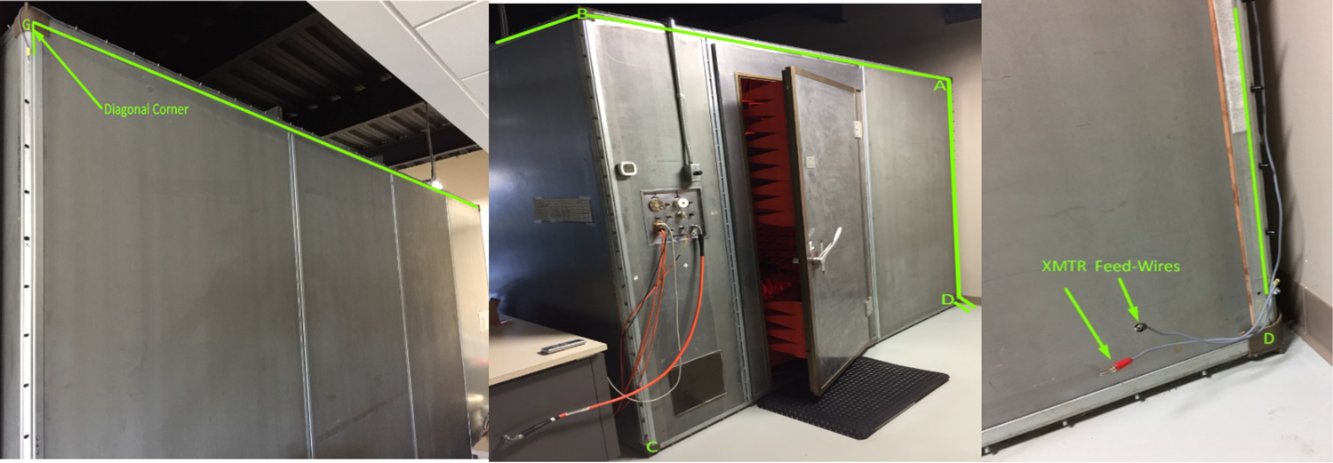
Careful attention must be given to the connection and dress of the Transmitter feed wires. For all Transmitter feed wire configurations used, the Transmitter is connected at diagonally opposite corners of the tested structure. Connecting across diagonal corners will provide the most evenly distributed signal coverage across the structure. By convention, the Transmitter is physically located at and connected to the front wall, which is defined as the most accessible and is typically where the door is located. The second Transmitter feed wire should be dressed along the enclosure’s vertical and horizontal edges to a connection point at the opposite diagonal corner (see Figure 3 for an actual setup). Use approximately 12 inches of No. 12AWG insulated, stranded wire for the short cable and as much as necessary for the long cable. If a bolt or screw head is not available for attaching the feed wires’ ends, drill and tap the nearest frame member. Do not tap through the panel. These feed wires can be installed permanently if desired to facilitate future testing. The polarity of the connections is inconsequential.


To perform enclosure probing, first examine all six surfaces inside the enclosure with the door closed. Initially adjust the Receiver audio volume knob and gain setting to its maximum (highest sensitivity), then adjust both down as necessary to accommodate the environment. Holding the Receiver so that the probe tip is as close as possible to and perpendicular to the wall (floor, ceiling, or one of the four sides), move the unit slowly (about six inches a second) down each seam. Stop when a sharp increase in the audible signal level is heard, or when the displayed value fluctuates noticeably, record the seam position, the distance of the apparent leak from the nearest active feed wire, and the Receiver reading. For optimum sensitivity, the probe should be perpendicular to the surface being tested. The Receiver units are on a logarithmic scale. When taking measurements, the value indicated on the Receiver display is in relative SUs.
No matter which standards must be met, selecting the right Shielding Effectiveness Leakage Detector is the key to ensuring commercial electronics and military EMI rooms are adequately shielded and are in compliance with standards.
So, AR has all the technical expertise and Shielding Effectiveness Leakage Detector System that you need to meet the MIL-STD-188/125 requirements. To learn more about AR SELDS system, feel free to contact one of our applications engineers at 800-933-8181 or visit our website at www.arworld.us.
160 Schoolhouse Rd.
Souderton PA 18964-9990 USA
215.723.8181
[email protected]
[email protected]
Contact Us
For an applications engineer call:
800.933.8181
For Customer Service, call:
215.723.0275
For Faxing Orders:
866.859.0582 (Orders Only, Please)
Privacy Policy
Terms of Use
Copyright ©2023 AR Inc.